Biomass material lock and working method

A biomass and material lock technology, applied in the field of biomass material lock, can solve problems such as fluctuations in the working conditions of biomass incinerators or biomass gasifiers, incineration feeding systems, explosions, etc., to achieve comprehensive utilization of energy and applicable materials Wide range of effects and reliable system

Active Publication Date: 2018-12-11
HARBIN BOILER
View PDF7 Cites 1 Cited by
  • Summary
  • Abstract
  • Description
  • Claims
  • Application Information

AI Technical Summary

Problems solved by technology

[0002] Biomass power generation technology is an advanced energy-saving and environmentally friendly power generation technology. According to the technical route, it is divided into biomass direct combustion power generation technology, biomass co-combustion power generation technology and biomass gasification power generation technology. The stability and safety of the biomass feeding system have high requirements. If there are problems such as blockage and high-temperature flue gas backflow in the biomass feeding system, it will not only affect the operation of the biomass incinerator or biomass gasifier, but also Cause safety accidents such as fire or even explosion in the feeding system
[0003] There are still two probl

Method used


Image

  • Biomass material lock and working method

Examples


Embodiment 1

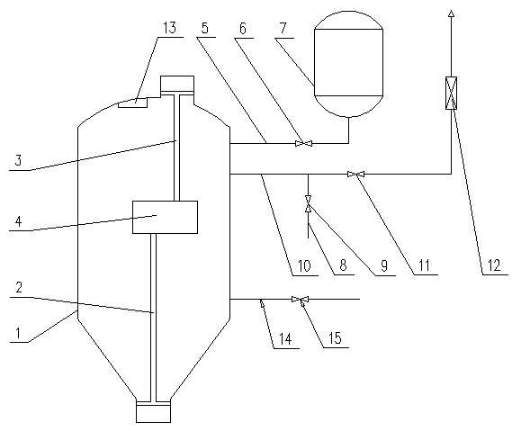
[0021] A biomass material lock, which consists of: a housing 1, a discharge valve 2 is installed inside the housing, the discharge valve is connected to the feed valve 3 through a transmission mechanism 4, and the housings are respectively It is connected with the primary pressure relief pipeline 5, the secondary pressure relief pipeline 10, and the air seal pipeline 14, the primary pressure relief pipeline is connected with the buffer tank 7, and the secondary pressure relief pipeline is connected with the The dust remover 12 is connected with the secondary charging pipeline 8, and a feed valve and a material level monitor 13 are installed inside the housing, and the material level monitor is located at the top of the housing, and the feed valve The feed valve is connected with the discharge valve 2 through the transmission mechanism 4, and a material level monitor is installed on the top of the housing.

Embodiment 2

[0023] According to the biomass lock described in Embodiment 1, a primary pressure relief valve 6 is installed on the primary pressure relief pipeline, and a secondary pressure relief valve 11 is installed on the secondary pressure relief pipeline. A secondary charging valve 9 is installed on the secondary charging pipeline, and a gas sealing valve 15 is installed on the gas sealing pipeline.

Embodiment 3

[0025] According to the biomass lock described in embodiment 1 or 2, the housing is provided with a feed inlet, a feed outlet, a maintenance hole, a primary charging and pressure releasing hole, a secondary charging and pressure releasing hole and an air seal hole.


PUM


Abstract

The invention provides a biomass material lock and a working method. Blockage, high temperature flue gas backflow and other problems of a biomass feeding system appear, not only are the operation of abiomass incinerator or a biomass gasifier influenced, but also feeding system catching fire, even explosion, and other safety accidents are caused. The biomass feeding lock includes a shell (1), a discharge valve (2) is installed in the shell, and the discharge valve is connected with a feeding valve (3) through a drive mechanism (4); the shell is correspondingly connected with a primary pressurecharging and relief pipeline (5), a secondary pressure relief pipeline (10), an air seal pipeline (14), wherein the primary pressure charging and relief pipeline is connected with a buffer tank (7),the secondary pressure relief pipeline is correspondingly connected with a dust remover (12), and a secondary pressure charging pipeline (8); and the feeding valve and a material level monitor (13) are installed in the shell, the material level is located at the top of the interior of the shell, the feeding valve is connected with the discharge valve (2) through the drive mechanism (4), and the material level monitor is installed at the top of the interior of the shell. The biomass material lock and the working method are used in a feeding system of biomass power generation.

Description

Technical field: [0001] The invention relates to a biological material lock. Background technique: [0002] Biomass power generation technology is an advanced energy-saving and environmentally friendly power generation technology. According to the technical route, it is divided into biomass direct combustion power generation technology, biomass co-combustion power generation technology and biomass gasification power generation technology. The stability and safety of the biomass feeding system have high requirements. If there are problems such as blockage and high-temperature flue gas backflow in the biomass feeding system, it will not only affect the operation of the biomass incinerator or biomass gasifier, but also Cause the feeding system to catch fire or even explode and other safety accidents. [0003] There are still two problems in the existing biomass feeding system: (1) Blockage of the feeding system: most biomass power generation systems require the continuity of t...

Claims


Application Information

Patent Timeline
IPC IPC(8): F23K3/00
CPCF23K3/00
Inventor 张彦军于强胡鹏龙魏国华
Owner HARBIN BOILER
Why Eureka
Try Eureka