External trigger device and external trigger method based on serial receiver, and oscilloscope

An external trigger and receiver technology, applied in the field of electrical signal processing, can solve the problems of low processing efficiency, increased design cost and hardware cost, increased processing time, etc., and achieve the effect of simplifying the circuit structure, simplifying the execution process, and improving the triggering accuracy.

Inactive Publication Date: 2018-12-11
SHENZHEN CITY SIGLENT TECH
View PDF5 Cites 5 Cited by
  • Summary
  • Abstract
  • Description
  • Claims
  • Application Information

AI Technical Summary

Problems solved by technology

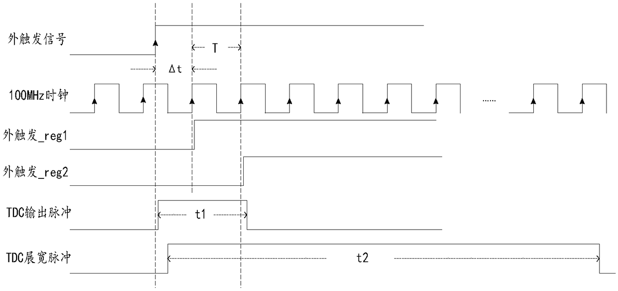
[0007] Although the TDC circuit can be used to solve the problem of time accuracy mismatch between the sampling rate of the external trigger signal and the sampling rate of the signal to be detected, it is necessary to add a TDC circuit on the hardware, which will bring about an increase in design cost and hardware cost. , which is not conducive to widespread promotion and application; in addition, it will also bring about the problem of low processing efficiency on the software. When using a TDC circuit, each external trigger needs to go through the process of TDC pulse stretching calculation, and the charging and discharging waiting process of the TDC circuit The time interval between two uses will be extended. At this time, the processing time of the software will be increased for each external trigger. In severe cases, the overall computing efficiency of the system will be reduced and the user's operating experience will be affected.

Method used


Image

  • External trigger device and external trigger method based on serial receiver, and oscilloscope
  • External trigger device and external trigger method based on serial receiver, and oscilloscope
  • External trigger device and external trigger method based on serial receiver, and oscilloscope

Examples


Embodiment Construction

[0050] The present invention will be further described in detail below through specific embodiments in conjunction with the accompanying drawings. Wherein, similar elements in different implementations adopt associated similar element numbers. In the following implementation manners, many details are described for better understanding of the present application. However, those skilled in the art can readily recognize that some of the features can be omitted in different situations, or can be replaced by other elements, materials, and methods. In some cases, some operations related to the application are not shown or described in the description, this is to avoid the core part of the application being overwhelmed by too many descriptions, and for those skilled in the art, it is necessary to describe these operations in detail Relevant operations are not necessary, and they can fully understand the relevant operations according to the description in the specification and genera...


PUM


Abstract

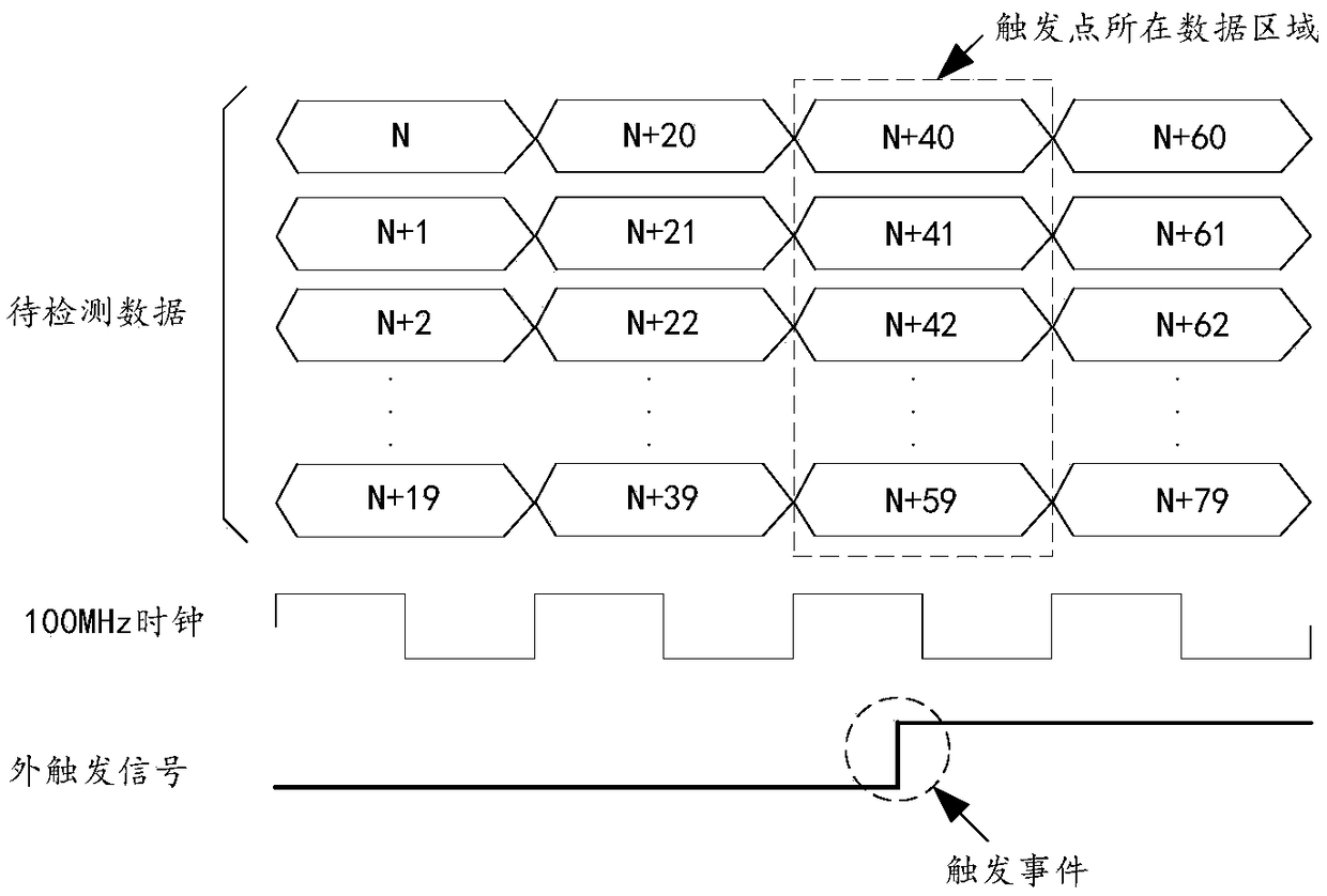
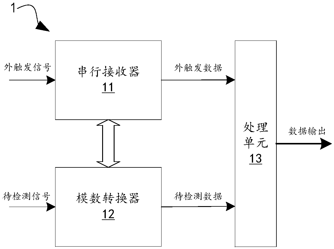
An external trigger device and an external trigger method based on a serial receiver, and an oscilloscope are disclosed. The external trigger device comprises the serial receiver used for acquiring external trigger data, an analog-digital converter used for acquiring data to be detected, and a processing unit used for determining a trigger point. On one hand, the sampling rate of the serial receiver to an external trigger signal is set to be the integral multiple of the sampling rate of the analog-digital converter to the signal to be detected so that the processing unit can correspond each data point in the data to be detected to one or more data points in the external trigger data in a parallel processing data process; when one data point in the external trigger data generates a triggerevent, the corresponding data point in the data to be detected can be conveniently found and the corresponding data point is taken as a trigger point; on the other hand, a traditional TDC circuit is not adopted so that the circuit structure of an external trigger device and the execution process of an external trigger method are simplified, trigger precision is guaranteed and simultaneously the hardware cost of a system is reduced.

Description

technical field [0001] The invention relates to the field of electrical signal processing, in particular to an external trigger device based on a serial receiver, an external trigger method, and an oscilloscope. Background technique [0002] Some signal detection devices often have a signal acquisition channel and an external trigger channel. The former is used to collect external signals to be detected, and the latter is used to collect external trigger analog signals to mark the signals to be detected when a trigger event occurs. Channels can be found in the CH channel and EXT TRIG channel on the control panel of the digital oscilloscope. [0003] At present, the working principle of the external trigger function in the signal detection equipment on the market is: the external trigger signal is input to the analog comparator inside the device through the external trigger channel, and compared with the trigger level set by the user. When the input signal is greater than the...

Claims


Application Information

Patent Timeline
Patent Type & Authority Applications(China)
IPC IPC(8): G01R13/02
CPCG01R13/0209G01R13/0254
Inventor 阮仲华蔡臻昱宋民
Owner SHENZHEN CITY SIGLENT TECH
Why Eureka
Try Eureka