Battery insulation detection circuit and control method thereof

A detection circuit and control method technology, applied in the direction of measuring electricity, measuring devices, measuring electrical variables, etc., can solve the problems of low detection accuracy of negative insulation resistance, poor actual use, long data processing time, etc., and achieve real-time performance Good, low hardware cost, high precision effect

Pending Publication Date: 2018-12-11
浙江慧众智能装备科技有限公司
View PDF8 Cites 5 Cited by
  • Summary
  • Abstract
  • Description
  • Claims
  • Application Information

AI Technical Summary

Problems solved by technology

In the existing insulation detection for DC charging, the detection accuracy of positive insulation resistance is usually high and the error is small, while the detection accuracy of negative insulation resistance is low and the error is large. The data processing time is long, and the actual usage is not good

Method used


Image

  • Battery insulation detection circuit and control method thereof
  • Battery insulation detection circuit and control method thereof
  • Battery insulation detection circuit and control method thereof

Examples


Embodiment

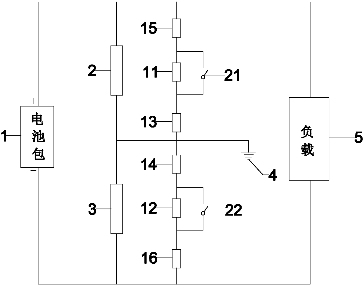
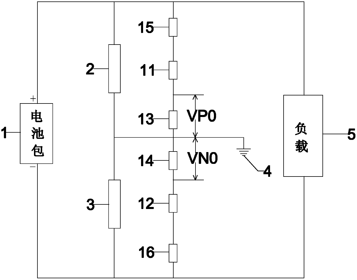
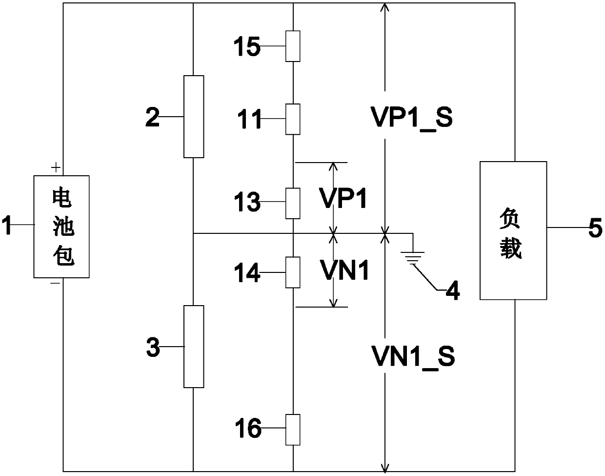
[0033] Such as figure 1 As shown in -5, the present invention is a battery insulation detection circuit, which is characterized in that it includes a battery pack 1, a positive insulation resistance 2, a negative insulation resistance 3, a first resistor 11, a second resistor 12, a third resistor 13, a Four resistors 14, a load resistor 5, a first controllable switch 21, and a second controllable switch 22, wherein: one end of the positive insulation resistor 2 is connected to one end of the first resistor 11, the first controllable switch 21 is connected to one end of the load resistor 5, and its common end is connected to the positive output terminal of the battery pack 1; the other end of the first resistor 11 is connected to the other end of the first controllable switch 21 , whose common end is connected to one end of the third resistor 13; the other end of the positive insulation resistor 2 is connected to the other end of the third resistor 13, one end of the negative i...


PUM


Abstract

The invention relates to a battery insulation detection circuit and a control method thereof. The battery insulation detection circuit is characterized by comprising a battery pack, a positive insulation resistor, a negative insulation resistor, a first resistor, a second resistor, a third resistor, a fourth resistor, a first controllable switch and a second controllable switch, wherein the positive insulation resistor is connected to one end of the first resistor, one end of the first controllable switch and one end of a load resistor; the common end of the positive insulation resistor, the first resistor, the first controllable switch and the load resistor is connected to the positive end of the battery pack; the other end of the first resistor is connected to the other end of the firstcontrollable switch; the common end of the first resistor and the first controllable switch is connected to one end of the third resistor; the other end of the positive insulation resistor is connected to the other end of the third resistor, one end of the negative insulation resistor, one end of the fourth resistor; the common end of the positive insulation resistor, the third resistor, the negative insulation resistor, and the fourth resistor is grounded; the other end of the negative insulation resistor is connected with one end of the second resistor, one end of the second controllable switch and the other end of the load resistor; the common end of the negative insulation resistor, the second resistor, the second controllable switch and the load resistor is connected to the negative end of the battery pack; the other end of the second resistor is connected to the other end of the second controllable switch; and the common end of the second resistor and the second controllable switch is connected to the other end of the fourth resistor. The battery insulation detection circuit is simple in structure, good in real-time performance and high in detection precision.

Description

technical field [0001] The invention relates to the field of insulation detection, in particular to a battery insulation detection circuit. Background technique [0002] With the continuous development of electric vehicles, more and more attention has been paid to the insulation performance of electric vehicles. At present, the high-frequency injection method is usually used to detect the insulation resistance of the whole vehicle (the resistance between the negative pole of the battery pack and the body). The high-frequency injection method is to inject high-frequency AC signals into the electrical system, and then calculate the insulation resistance value by calculating its amplitude or phase. However, injecting AC signals into the DC system actually introduces a source of interference to the DC system, which affects the normal operation of the DC system and has complex circuits, high cost, and poor stability. In addition, the detection accuracy is affected by distributed...

Claims


Application Information

Patent Timeline
Patent Type & Authority Applications(China)
IPC IPC(8): G01R31/36
CPCG01R31/3648
Inventor 张云姜丹李强应骏李枫梁艺忠曾爽佘国华嵇伟平
Owner 浙江慧众智能装备科技有限公司
Why Eureka
Try Eureka