
Machining mold for prefabricated outer wall component

A technology for processing molds and components, applied in the field of processing molds for prefabricated exterior wall components, can solve the problems of increasing construction cost and waste, and the inability of molds to be universal.

Active Publication Date: 2018-12-14
CHENGDU JIANGONG INDZATION BUILDING CO LTD
View PDF10 Cites 8 Cited by
  • Summary
  • Abstract
  • Description
  • Claims
  • Application Information

AI Technical Summary

Problems solved by technology

The new prefabricated building is an ideal way. The prefabricated building is like industrial manufacturing, and the required parts are produced and then assembled into industrial equipment; the industrialized prefabricated building also has parts, and its prefabricated parts are also in the The factory first uses molds to produce various prefabricated concrete components such as walls, floors, beams, columns, etc., and transports them to the construction site to assemble them into buildings. However, buildings have different shapes and sizes, so different molds are required to complete the prefabrication. Parts manufacturing requires a large number of molds, but the molds cannot be used for one prefabricated part and one set of molds, which greatly increases the construction cost and waste, which has always plagued the assembly construction industry

Method used


Image

  • Machining mold for prefabricated outer wall component
  • Machining mold for prefabricated outer wall component
  • Machining mold for prefabricated outer wall component

Examples


Embodiment 1

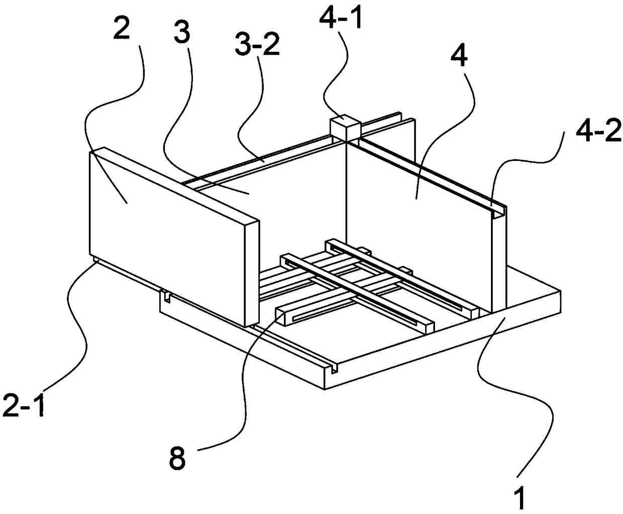
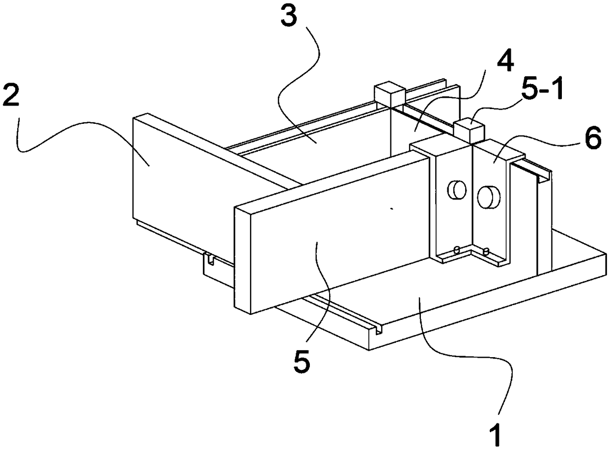
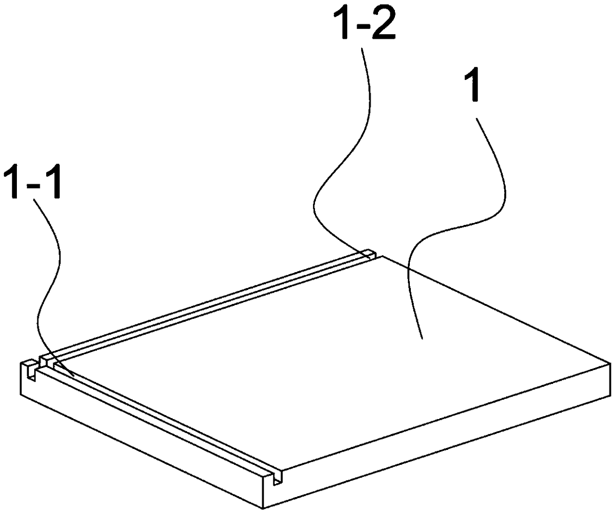
[0033] Such as Figure 1-5 As shown, a processing mold for prefabricating exterior wall components includes a bottom form 1 and a first side form 2, a second side form 3, a third side form 4 and a fourth side form that are slidably arranged on the top of the bottom form 1 5; the top of the bottom mold 1 is provided with a first chute 1-1 along its length direction, and a second chute 1-2 is provided along its width direction; the bottom of the first side mold 2 is provided with the The first slider 2-1 matching the first chute 1-1, the bottom of the second side mold 3 is provided with a second slider 3-1 matching the second chute 1-2 The top of the second side mold 3 is provided with a third chute 3-2, and the third side mold 4 is provided with a third slider 4-1 matching the third chute 3-2 The top of the third side mold 4 is provided with a fourth chute 4-2, and the fourth side mold 5 is provided with a fourth slider 5-1 matching the fourth chute 4-2 ; the first side mold ...

Embodiment 2

[0036] Such as Figure 5 As shown, this embodiment is based on Embodiment 1, the connecting device 6 includes a connecting piece 6-1 and a locking screw 6-2 for fixing the connecting piece 6-1, and the connecting piece 6-1 includes The first connecting part 6-3, the second connecting part 6-4, the third connecting part 6-5, the first buckling part 6-6 and the second buckling part 6-7, the first connecting part 6- One end of 3 is vertically affixed to the second connecting portion 6-4, and the first fastening portion 6-6 is vertically affixed to the other end of the first connecting portion 6-3; the third connecting portion One end of 6-5 is vertically fixed to the second connecting part 6-4, and the side of the third connecting part 6-5 is vertically fixed to the side of the first connecting part 6-3. The other end of the second engaging portion 6-7 is vertically fixed to the third connecting portion 6-5.

[0037] The connecting piece 6-1 is integrally cast, wherein one end ...

Embodiment 3

[0039] Such as Figure 1-5 As shown, this embodiment is based on Embodiment 1, and scales are provided on the tops of the first side form 2 , the second side form 3 , the third side form 4 and the fourth side form 5 . The purpose of setting the ruler is to facilitate more precise adjustment of the size, and at the same time, it is convenient for the user to check whether the size is within a reasonable range and make further adjustments.


PUM


Abstract

The invention discloses a machining mold for a prefabricated outer wall component. The machining mold comprises a bottom mold, a first side mold, a second side mold, a third side mold and a fourth side mold, wherein the first side mold, the second side mold, the third side mold and the fourth side mold are arranged at the top of the bottom mold in a sliding mode; a first sliding groove is formed in the top of the bottom mold along the length direction of the bottom mold, and a second sliding groove is formed along the width direction of the bottom mold; a first sliding block matched with the first sliding groove is arranged at the bottom of the first side mold, and a second sliding block matched with the second sliding groove is arranged at the bottom of the second side mold; a third sliding groove is formed in the top of the second side mold, and a third sliding block matched with the third sliding groove is arranged on the third side mold; and a fourth sliding groove is formed in thetop of the third side mold, and a fourth sliding block matched with the fourth sliding groove is arranged on the fourth side mold. The outer walls with different sizes are poured by adjusting the first side mold, the third side mold and the fourth side mold, so that the adjustment is convenient, the whole machining mold is simple in structure.

Description

technical field [0001] The invention relates to the field of building construction molds, in particular to a processing mold for prefabricating exterior wall components. Background technique [0002] At present, the country strengthens green, environmental protection and energy-saving buildings. The new prefabricated building is an ideal way. The prefabricated building is like industrial manufacturing, and the required parts are produced and then assembled into industrial equipment; the industrialized prefabricated building also has parts, and its prefabricated parts are also in the The factory first uses molds to produce various prefabricated concrete components such as walls, floors, beams, columns, etc., and transports them to the construction site to assemble them into buildings. However, buildings have different shapes and sizes, so different molds are required to complete the prefabrication. Parts manufacturing requires a large number of molds, but the molds cannot be...

Claims


Application Information

Patent Timeline
Patent Type & Authority Applications(China)
IPC IPC(8): B28B7/22
CPCB28B7/22
Inventor 王虎彭钦魏英杰王旭李蒙舒勤闫洪坤杨雪李颖颖安偲玮袁尉航唐柏林
Owner CHENGDU JIANGONG INDZATION BUILDING CO LTD
Learn More