
L-shaped groove type cement drill

A technology of cement and drill bits, which is applied in the direction of stone processing tools, manufacturing tools, stone processing equipment, etc., can solve the problems of high production cost, slow discharge of cement drill bits, and single groove of drill bits, so as to reduce waste and defective products and reduce contact Area, the effect of ensuring product quality

Pending Publication Date: 2018-12-14
舟山飞达工具有限公司
View PDF0 Cites 0 Cited by
  • Summary
  • Abstract
  • Description
  • Claims
  • Application Information

AI Technical Summary

Problems solved by technology

[0003] The existing drill bits generally have the following disadvantages: 1. The groove type of the existing drill bit is single; 2. The excretion of the cement drill bit is slow during work; 3. The production cost of the product used in China is high; 4. The resistance received during use is large

Method used


Image

  • L-shaped groove type cement drill
  • L-shaped groove type cement drill
  • L-shaped groove type cement drill

Examples


Embodiment Construction

[0018] Specific embodiments of the present invention will be described in detail below for further understanding of the present invention.

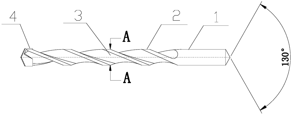
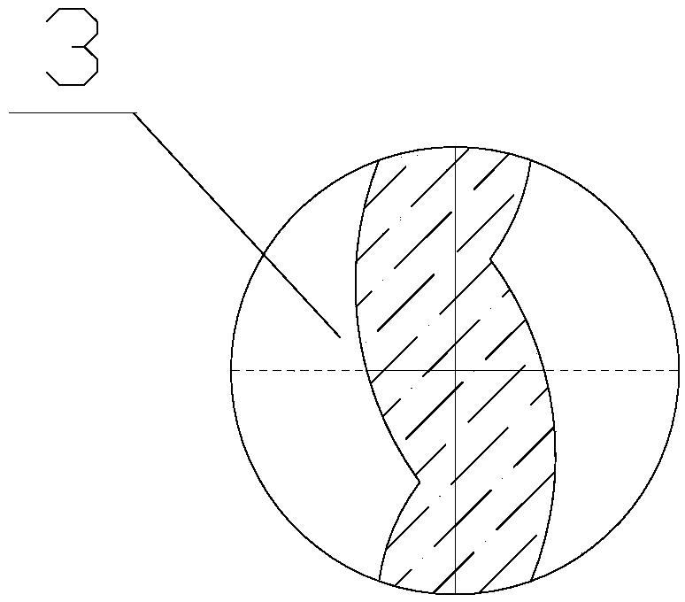
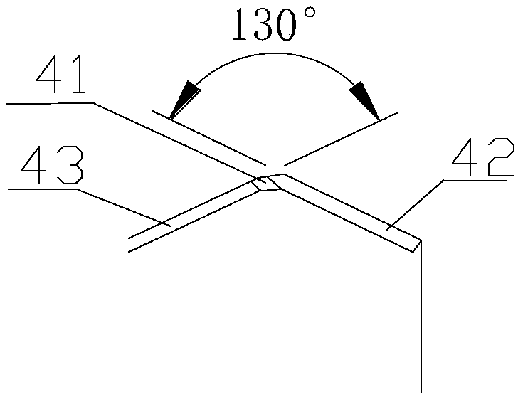
[0019] figure 1 It is a schematic diagram of the L-groove cement drill of the present invention. figure 2 for figure 1 The A-A section view of the L-groove cement drill. image 3 It is a schematic diagram of the drill bit of the L-groove cement drill of the present invention. as the picture shows:

[0020] An L-groove cement drill, comprising a drill rod 1 and a working section 2 arranged at the front end of the drill rod 1, the working section 2 is provided with a chip removal groove 3, and the groove type of the chip removal groove 3 is L-shaped , the front end of the working section 2 is provided with a drill bit 4, the drill bit 4 extends forward to form a head of a conical structure, the head is composed of a plurality of inclined surfaces connected to each other, and the included angle of the head is 130 degrees .

[0021] Pr...


PUM


Abstract

The invention discloses an L-shaped groove type cement drill. The L-shaped groove type cement drill comprises a drill rod and a working section, wherein the working section is arranged at the front end of the drill rod; the working section is provided with a chip removal groove, the groove shape of the chip removal groove is an L shape, and a drill bit is arranged at the front end of the working section; and the drill bit extends forwards to form a head of a conical structure, the head is formed by a plurality of inclined planes which are mutually connected, and an included angle of the head is 130 degrees. According to the L-shaped groove type cement drill, the chip removal effect is enhanced by changing the groove shape, meanwhile, due to the fact that the groove shape is changed, forcestressing can be easier, and the arrangement of an angle of a groove hook enables the drilling speed to be higher; meanwhile, the drill bit of the L-shaped groove type cement drill is more energy-saving and environment-friendly; and advantages are provided for creating competition for clients at home and abroad, waste products and inferior products are reduced, and the benefits of the clients aremaximized.

Description

technical field [0001] The invention relates to the field of construction tools, in particular to an L-groove cement drill. Background technique [0002] The drill bit is a common tool for drilling and reaming. When the drill bit is drilling, it mainly cuts the workpiece through the top of the cutter head, and discharges the debris through the chip discharge groove. If the debris cannot be discharged smoothly, it will cause the drill Scratches appear on the inner wall of the hole, and even cause the workpiece to become a waste product. When designing the drill bit, the shape and structure of the chip removal flute will directly affect the speed and effect of chip removal. The shape and structure of the drill tip also determines the speed of positioning and cutting of the drill. [0003] Existing drill bits generally have the following disadvantages: 1. The groove type of the existing drill bit is single; 2. The excretion of the cement drill bit is slow during work; 3. The p...

Claims


Application Information

Patent Timeline
Patent Type & Authority Applications(China)
IPC IPC(8): B28D1/14
CPCB28D1/146
Inventor 楼俊劭
Owner 舟山飞达工具有限公司
Learn More