
Pneumatic assisting press

A technology for booster mechanisms and presses, which is applied to stamping machines, presses, manufacturing tools, etc. It can solve the problems that the pneumatic machine is difficult to meet the processing requirements and the output force is small, so as to solve the problem of limited output force of the cylinder and reduce energy consumption. Effect

Inactive Publication Date: 2018-12-14
朱继雷
View PDF8 Cites 2 Cited by
  • Summary
  • Abstract
  • Description
  • Claims
  • Application Information

AI Technical Summary

Problems solved by technology

However, compared with the hydraulic machine, the output force of the pneumatic machine is small. When the required output stroke is short and the required output force is relatively large, it is difficult for the pneumatic machine itself to meet the processing requirements.

Method used


Image

  • Pneumatic assisting press

Examples


Embodiment Construction

[0013] The present invention will be described in further detail below in conjunction with the embodiments of the drawings.

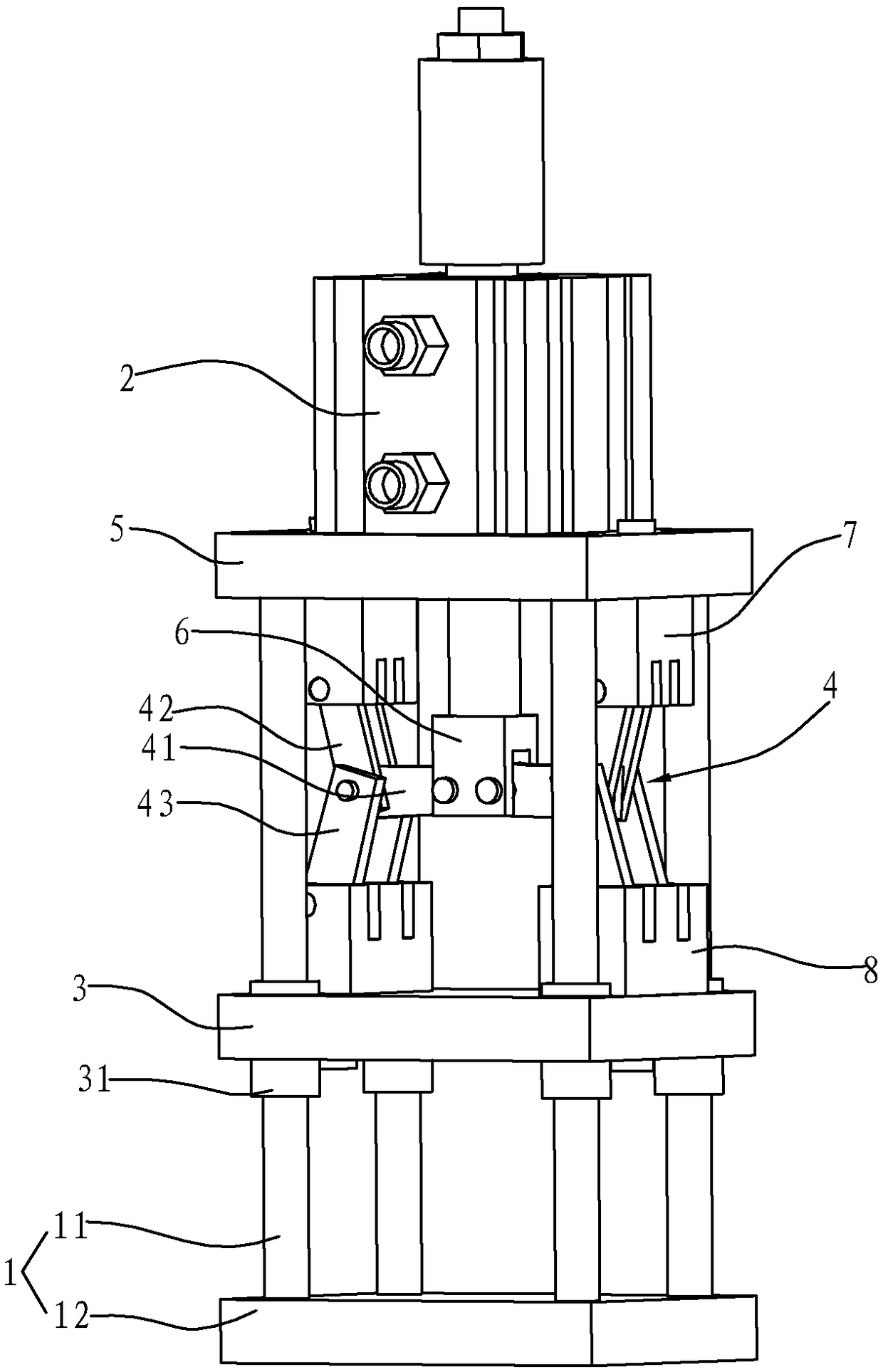
[0014] Such as figure 1 As shown, the pneumatic booster press in this embodiment includes a frame 1, a cylinder 2, a mounting plate 5, a connecting plate 3, and a boosting mechanism 4.

[0015] The frame 1 includes a base 12 and a guide post 11 connected to the base 12. In this embodiment, there are four guide posts 11 parallel to each other, and the four guide posts 11 are arranged perpendicular to the base 12. The top ends of the four guide posts 11 are fixedly connected to the mounting plate 5. In this embodiment, the four corners of the mounting plate 5 are provided with holes matching the diameter of the guide post 11, and the four guide posts 11 are respectively fixedly connected in the corresponding holes to realize the fixed connection of the mounting plate 5 on the top of the guide post.

[0016] The cylinder 2 is fixedly arranged on the upper plate...


PUM


Abstract

The invention relates to a pneumatic assisting press. The pneumatic assisting press comprises a rack and an air cylinder installed on the rack. The rack is provided with at least two parallel guide columns, the guide columns are connected with a connecting plate in a sliding manner, the air cylinder is in driving connection with the connecting plate, and an assisting mechanism which can increase the output force of the connecting plate is further connected between the output end of the air cylinder and the connecting plate. The assisting mechanism is connected with the output end of the air cylinder. The assisting mechanism is installed on the connecting plate and can push the connecting plate to do reciprocating motion on the guide columns. The pneumatic assisting press is additionally provided with the assisting mechanism, by means of the action of the assisting mechanism, output force multiple times the output force of the air cylinder can be output to the connecting plate, during working, the connecting plate is provided with a die or a plunger chip and other working components, machining, press fitting or assembling of parts are completed. In this way, the requirement that machining needs relatively large output force can be met, the problem that the output force of the air cylinder is limited is solved. When relatively small output force is needed, the energy consumptionof the air cylinder can be reduced.

Description

Technical field [0001] The invention relates to a pneumatic booster press. Background technique [0002] Stamping technology is currently one of the widely used metal pressure processing methods, which is widely used in the pressing and assembly of various small parts. Existing presses include hydraulic presses and pneumatic presses according to different power sources. The output power of the hydraulic press is large, but during use, the hydraulic press will inevitably have oil leakage, and it is difficult to use the hydraulic press under high and low temperature conditions. At the same time, in order to prevent a large amount of oil leakage, hydraulic components require high manufacturing precision, and it is not easy to check for failures during use, which brings certain difficulties to use and maintenance, and the maintenance of hydraulic equipment requires experience, and the training of hydraulic technicians takes a long time. . [0003] When the processing requires a smal...

Claims


Application Information

Patent Timeline
Patent Type & Authority Applications(China)
IPC IPC(8): B30B1/16
CPCB30B1/16
Inventor 朱继雷
Owner 朱继雷
Learn More