
Converter system and control method thereof

A control method and flow system technology, applied in the direction of converting AC power input to DC power output, power transmission AC network, output power conversion device, etc., can solve capacitor overvoltage, limited auxiliary commutation voltage output, and complex control And other issues

Pending Publication Date: 2022-05-13
TSINGHUA UNIV
View PDF0 Cites 0 Cited by
  • Summary
  • Abstract
  • Description
  • Claims
  • Application Information

AI Technical Summary

Problems solved by technology

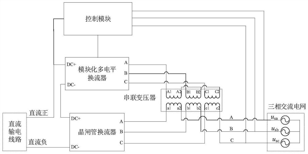
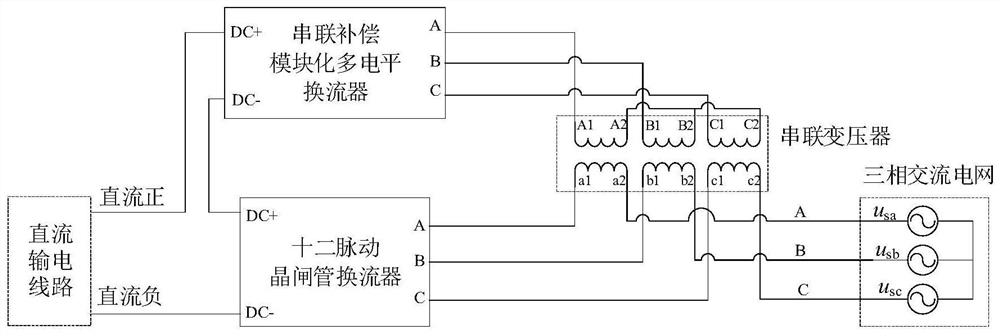
[0007] Therefore, the first purpose of this disclosure is to propose a commutation system to solve the problem of complex control in the prior art when using voltage sub-modules to resist commutation failures, and the problem of sub-module capacitor overvoltage or undervoltage causes Auxiliary commutation voltage output limited problem

Method used


Image

  • Converter system and control method thereof
  • Converter system and control method thereof
  • Converter system and control method thereof

Examples


Embodiment Construction

[0041] Reference will now be made in detail to the exemplary embodiments, examples of which are illustrated in the accompanying drawings. When the following description refers to the accompanying drawings, the same numerals in different drawings refer to the same or similar elements unless otherwise indicated. The implementations described in the following exemplary embodiments do not represent all implementations consistent with the embodiments of the present disclosure. Rather, they are merely examples of apparatuses and methods consistent with aspects of the disclosed embodiments as recited in the appended claims.

[0042] In the description of this specification, descriptions referring to the terms "one embodiment", "some embodiments", "example", "specific examples", or "some examples" mean that specific features described in connection with the embodiment or example , structure, material or characteristic is included in at least one embodiment or example of the present d...


PUM


Abstract

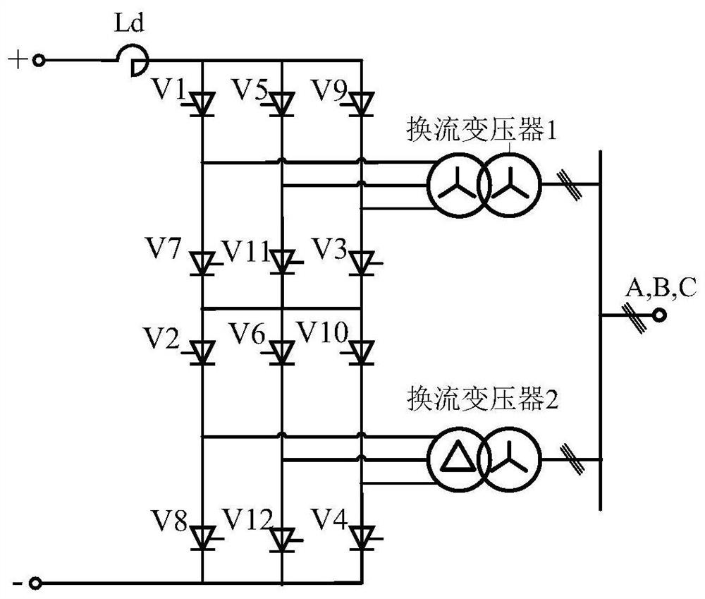
The invention provides a commutation system and a control method thereof. The commutation system comprises a main circuit module and a control module connected with the main circuit module. The main circuit module comprises a thyristor converter, a modularized multi-level converter and a series transformer, the direct current positive end of the thyristor converter is connected with the direct current negative end of the modularized multi-level converter, and the direct current negative end of the thyristor converter and the direct current positive end of the modularized multi-level converter are respectively connected with a direct current power transmission line; the series transformer comprises a primary winding and a secondary winding, the alternating current end of the modular multilevel converter is connected with the primary winding, and the alternating current end of the thyristor converter is connected with a three-phase alternating current power grid through the secondary winding; the thyristor converter converts current of a direct-current power transmission line into alternating current, and the control module obtains control pulse signals by utilizing voltage of a three-phase alternating-current power grid and capacitor voltage of all sub-modules of the modularized multi-level converter so as to control the modularized multi-level converter to achieve voltage compensation of the thyristor converter.

Description

technical field [0001] The present disclosure relates to the technical field of direct current transmission, in particular to a converter system and a control method thereof. Background technique [0002] The characteristics of the distribution of energy and load centers in my country determine that HVDC transmission is an important way to realize large-scale long-distance power transmission. Conventional direct current transmission technology (LCC-HVDC) based on thyristor converters (Line Commutated Converters, LCCs) has the advantages of low cost, high efficiency, and high voltage and capacity levels. It is still the main way of long-distance large-capacity power transmission. However, commutation failure has always been a common failure faced by the thyristor converter side. When the two valves in the thyristor converter are commutating, because the commutation process has not been completed, or after the valve that is expected to be shut off is turned off, the blocking ...

Claims


Application Information

Patent Timeline
IPC IPC(8): H02M7/483H02M7/521H02J3/36
CPCH02M7/483H02M7/521H02J3/36
Inventor 宋强曾嵘余占清赵彪李政轩屈鲁
Owner TSINGHUA UNIV
Learn More