Push device for conveniently conveying materials for electric massage chair production

A technology for pushing devices and conveying materials, applied in conveyor control devices, conveyor objects, conveyors, etc., can solve the problems of increasing the working time of staff, unable to prevent materials from falling, and reducing conveying efficiency, avoiding work Efficiency reduction, good conveying and pushing effect, and convenient operation effect

Inactive Publication Date: 2018-12-14
JIAXING WEITELA ELECTRICAL SCI & TECH CO LTD
View PDF0 Cites 0 Cited by
  • Summary
  • Abstract
  • Description
  • Claims
  • Application Information

AI Technical Summary

Problems solved by technology

[0002] The push device is a device that uses external force to save the physical strength of the staff, thereby improving the work efficiency of the staff, and the push device that is convenient for conveying materials speeds up the conveying of materials and improves the speed of material processing in enterprises. The traditional push device for conveying materials is in There are certain limitations in use, and the flexibility of use is not high. With the continuous development of industry, the driving device for conveying materials is also constantly updated, which is more convenient for people to use.
[0003] The existing push device for conveying materials has certain disadvantages in use. It cannot prevent the material from falling during the conveying process, which reduces the conveying efficiency and increases the working hours of the staff. The use of the traditional push device for conveying materials has limitations It is relatively space-consuming, which has brought certain adverse effects on people's use process. Therefore, we propose a push device that is convenient for the production and delivery of electric massage chairs.

Method used


Image

  • Push device for conveniently conveying materials for electric massage chair production
  • Push device for conveniently conveying materials for electric massage chair production
  • Push device for conveniently conveying materials for electric massage chair production

Examples


Embodiment Construction

[0017] In order to make the technical means, creative features, goals and effects achieved by the present invention easy to understand, the present invention will be further described below in conjunction with specific embodiments.

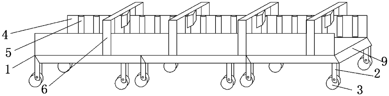
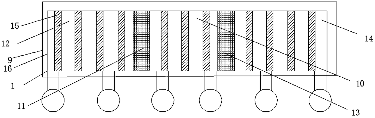
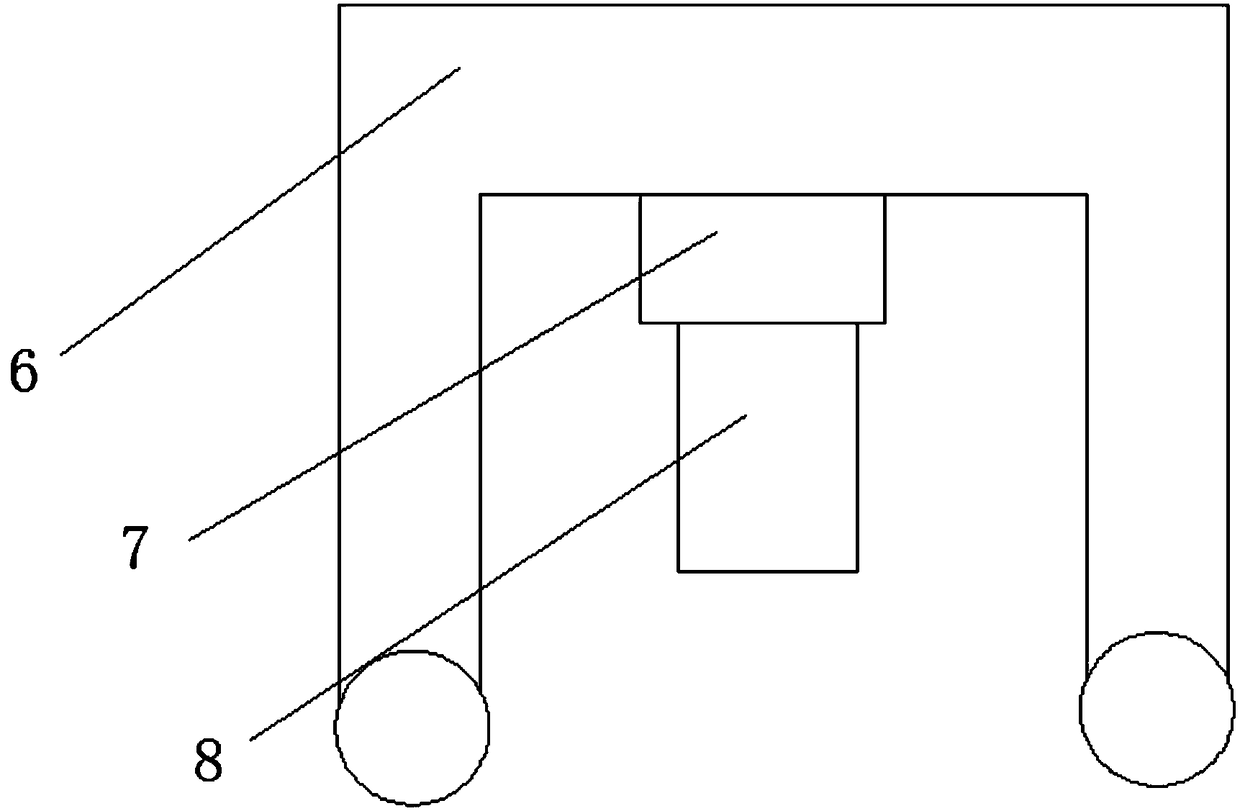
[0018] Such as Figure 1-3 As shown, a kind of pushing device that facilitates the production of electric massage chairs to transport materials includes a pushing device main body 1 and a conveying device 10, the lower end of the pushing device main body 1 is provided with a support rod 2, and the lower end of the supporting rod 2 is provided with Fold the universal wheel 3, the top of the main body of the pushing device 1 is provided with a protective side plate 4, and the inner surface of the protective side plate 4 is provided with an acceleration roller 5, and one side of the main body of the pushing device 1 is provided with a booster device 6, The lower end of the booster 6 is provided with a movable shaft 7, and the lower end of the movable...


PUM


Abstract

The invention discloses a push device for conveniently conveying materials for electric massage chair production. The push device comprises a push device main body and a conveying device I, wherein aprotective side plate is arranged above the push device main body, an accelerating roller is arranged on the inner surface of the protective side plate, a power assisting device is arranged on one side of the push device main body, a movable shaft is arranged on the lower end of the power assisting device, a push assisting device is arranged on the lower end of the movable shaft, a material conveying table is arranged in the push device main body, and a removable push plate is arranged on one side of the conveying device I. The push device for conveniently conveying the materials for electricmassage chair production is provided with the protective side plate, the accelerating roller, the power assisting device and the removable push plate, so that the materials can be prevented from falling in a conveying process, and the conveying efficiency is improved, thereby improving the working efficiency of working personnel, increasing the use flexibility of the conveying push device and saving the use space. The push device is suitable for different working conditions, and good use prospects are brought.

Description

technical field [0001] The invention relates to the field of material conveying equipment, in particular to a pushing device for facilitating the production and conveying of materials for electric massage chairs. Background technique [0002] The push device is a device that uses external force to save the physical strength of the staff, thereby improving the work efficiency of the staff, and the push device that is convenient for conveying materials speeds up the conveying of materials and improves the speed of material processing in enterprises. The traditional push device for conveying materials is in There are certain limitations in use, and the flexibility of use is not high. With the continuous development of industry, the driving device for conveying materials is also constantly updated, which is more convenient for people to use. [0003] The existing push device for conveying materials has certain disadvantages in use. It cannot prevent the material from falling dur...

Claims


Application Information

Patent Timeline
IPC IPC(8): B65G21/20B65G41/00B65G43/08
CPCB65G21/2063B65G41/008B65G43/08B65G2207/08
Inventor 朱桂林
Owner JIAXING WEITELA ELECTRICAL SCI & TECH CO LTD
Why Eureka
Try Eureka