Prefabricated panel connection structure of large double walls

A technology of connecting structure and double wall, applied in the direction of wall, building component, building structure, etc., can solve the problems of complex production process, high production cost, lower productivity, etc., to shorten construction period, save construction cost, and improve workability Effect

Inactive Publication Date: 2018-12-14
PCS技术株式会社 +1
View PDF0 Cites 0 Cited by
  • Summary
  • Abstract
  • Description
  • Claims
  • Application Information

AI Technical Summary

Problems solved by technology

[0007] However, with respect to this conventional large-scale double wall, it is necessary to go through the process of inserting the wire mesh 25 into each narrow gap of the vertical joint of the continuously assembled inner and outer prefabricated panels 21 one by one by the worker, thus requiring a lot of work. staff and time, thus being a major cause of greatly reduced productivity
[0008] In addition, in the process of manufacturing, transporting, and assembling a conventional large double-layer wall, it is necessary to integrate the inner and outer prefabricated panels so that they do not separate during handling, but also to withstand the time of concrete pouring after assembly. For the side pressure, there is a lightweight steel truss connection and reinforcement material between the inner and outer prefabricated panels, so it needs to go through the following process: When manufacturing, after reinforcing with one end of the connection reinforcement material embedded in the prefabricated panel on one side, The other end of the connection reinforcement material is embedded in the unreinforced concrete of the prefabricated panel on the opposite side by inverting the reverser, thereby integrating the inner and outer prefabricated panels. Therefore, there are disadvantages as follows: Very complex, concrete curing takes a lot of time and thus high production costs

Method used


Image

  • Prefabricated panel connection structure of large double walls
  • Prefabricated panel connection structure of large double walls
  • Prefabricated panel connection structure of large double walls

Examples


Embodiment Construction

[0028] Hereinafter, a preferred embodiment of the prefabricated panel connection structure of the large double-wall wall of the present invention will be specifically described with reference to the accompanying drawings.

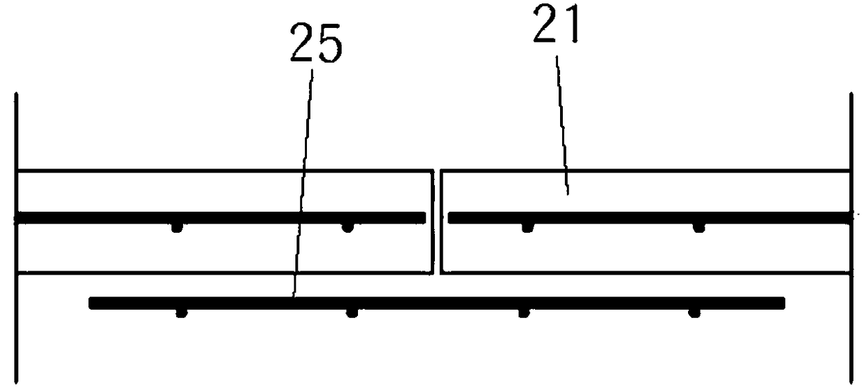
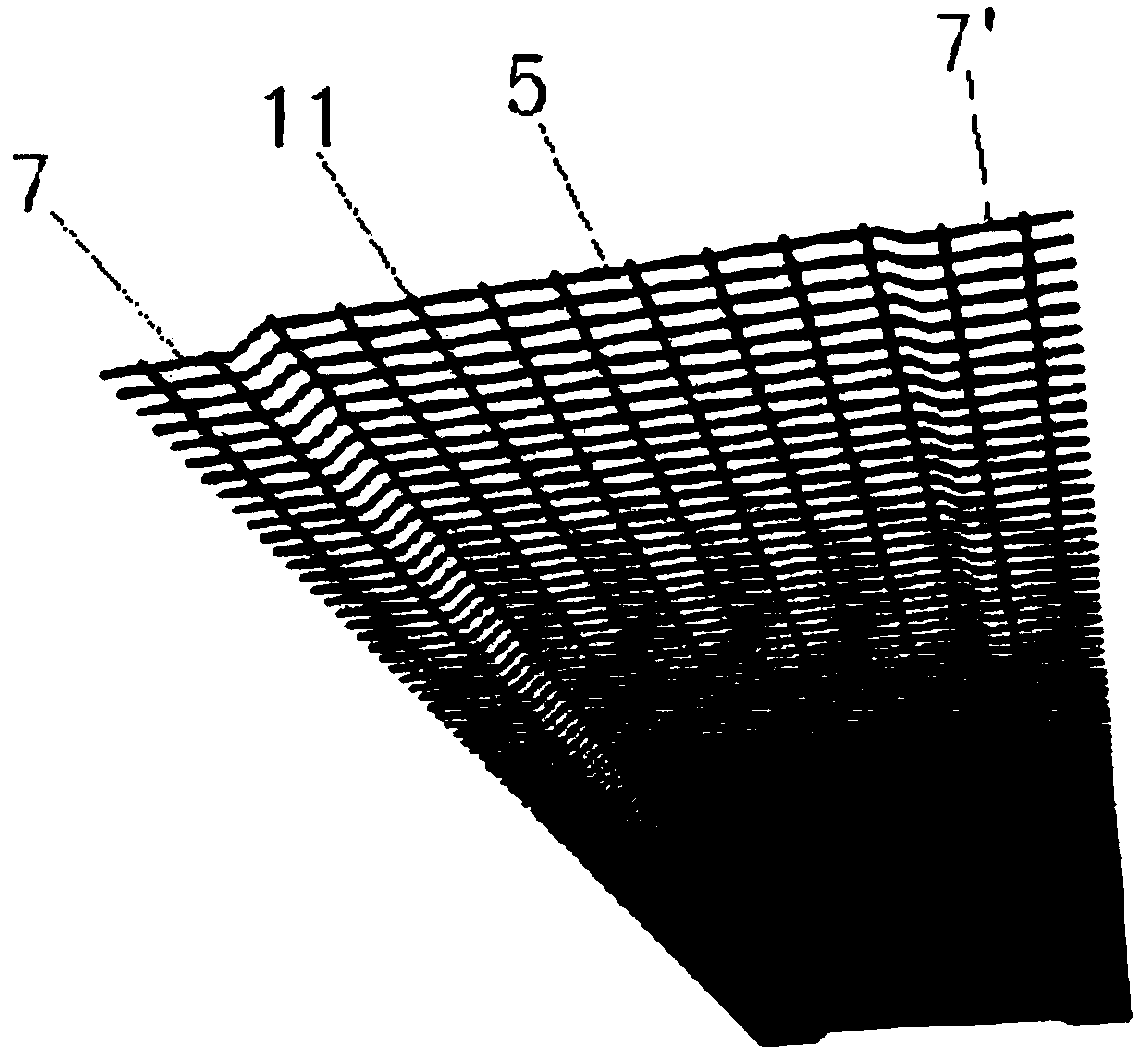
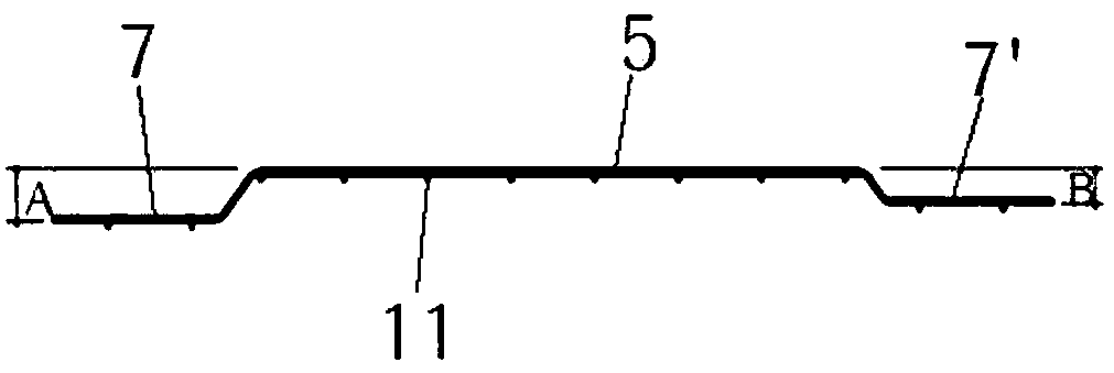
[0029] figure 2 It is an outline perspective view of a preferred embodiment of the wire mesh applicable to the present invention, image 3 is a cross-sectional view of copper, Figure 4 For the outline perspective view of the large-scale double-wall wall to which the present invention is applied, Figure 5 It is a perspective view showing the construction state of a large double wall to which the present invention is applied, Image 6 For the perspective view of the state that copper construction was finished, Figure 7 is the cross-sectional view of copper, such as Figure 4 As shown, in the large-scale double-wall prefabricated panel connection structure of the present invention, recessed parts 3, 3' are formed in the inner parts of the left and righ...


PUM


Abstract

The invention relates to the prefabricated panel connection structure of large double walls. The two end portions are embedded in inner and outer prefabricated panels in a protruded mode, and the leftand right end portions form the wire meshes of connection portions with a height difference. During the construction of the large double wall, the adjacent inner and outer prefabricated panels are automatically and mutually overlapped and combined by using the height difference of the connecting portions, concrete filled between the inner and outer prefabricated panels is used to make the adjacent large double walls mutually and firmly realize integration so as to improve workability. A construction period can be shortened, construction cost is greatly saved, and when the large double walls are made, the concrete is used to simultaneously pour the inner and outer prefabricated panels so as to achieve one body connection. Therefore, the inner and outer prefabricated panels can be simply and rapidly connected and construction cost is greatly saved.

Description

technical field [0001] The present invention relates to the connection structure of prefabricated panels of large double walls, for the connection of the inner and outer prefabricated panels of large double walls for the construction of thick and high concrete parapets and the vertical joints where these double walls meet double walls The connection that ensures the connection performance of the reinforcement becomes easier to improve workability and reduce construction costs. Background technique [0002] In general, a double-wall (double-wall) suitable for the construction of a concrete parapet has a pair of inner and outer prefabricated panels with a thickness of 6-7cm, and a connection formed by a steel bar such as a truss connection material is embedded at a predetermined interval. The shape of the reinforcing material. [0003] In this type of double wall, after reinforcing with one end of the connecting reinforcement material buried inside the prefabricated panel on ...

Claims


Application Information

Patent Timeline
Patent Type & Authority Applications(China)
IPC IPC(8): E04B2/86
CPCE04B2/8629E04B2/8652
Inventor 浏光浚
Owner PCS技术株式会社
Why Eureka
Try Eureka