
Flue gas waste heat recovery and utilization method

A technology of flue gas waste heat and recovery device, applied in heat exchangers, heat exchange equipment, heat exchanger types, etc., can solve the problems of exhaust gas loss, waste of resources, low thermal efficiency of boilers, etc., to achieve a high degree of automation and cost savings Effect

Active Publication Date: 2018-12-14
GUIZHOU HUANKE ENVIRONMENT ECOLOGICAL RES & DEV CO LTD
View PDF5 Cites 6 Cited by
  • Summary
  • Abstract
  • Description
  • Claims
  • Application Information

AI Technical Summary

Problems solved by technology

[0002] At present, for boilers, whether they are coal-fired boilers, gas-fired boilers, oil-fired boilers, or biomass boilers, there is a problem of low thermal efficiency. Among them, the loss of exhaust smoke is one of the most important reasons for the low thermal efficiency of boilers.
The temperature of the flue gas discharged from these boilers is as high as 90 degrees. The flue gas is directly discharged to the outside after environmental protection treatment, and the heat of the flue gas cannot be effectively used. my country is a large coal-fired country. There are tens of millions of tons of smoke and dust discharged, and the heat of the flue gas cannot be recovered, resulting in a great waste of resources. Therefore, the recovery of waste heat from flue gas has become the main research direction for improving the thermal efficiency of boilers.

Method used


Image

  • Flue gas waste heat recovery and utilization method
  • Flue gas waste heat recovery and utilization method

Examples


Embodiment Construction

[0022] The following is further described in detail through specific implementation methods:

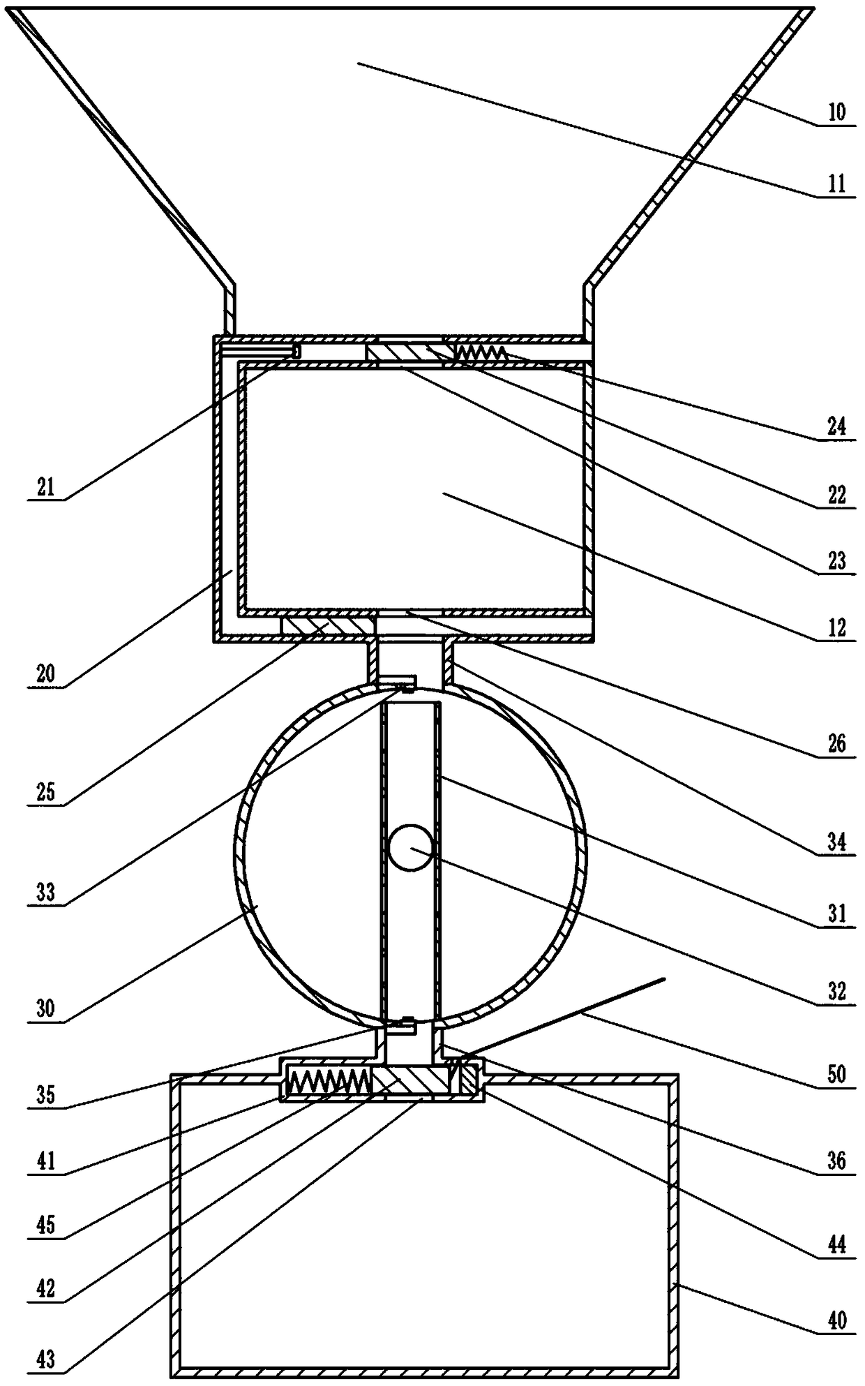
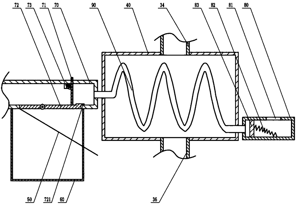
[0023] Instructions attached Figures 1 to 2 The reference signs in include: water storage tank 10, upper chamber 11, lower chamber 12, communicating pipe 20, second electromagnet 21, magnet 22, first port 23, first spring 24, slider 25, second port Port 26, heating cylinder 30, limit frame 31, floating ball 32, first single-control switch 33, first pipe 34, second single-control switch 35, second pipe 36, heat preservation water tank 40, fixed block 41, magnetic strip 42. Through hole 43, first electromagnet 44, tension spring 45, pull wire 50, dust box 60, straight line part 70, screen 71, flip plate 72, protrusion 721, brush handle 73, buffer channel 80, exhaust Port 81, second spring 82, piston 83, spiral part 90.

[0024] Such as figure 1 , figure 2 As shown, the flue gas waste heat recovery method uses a flue gas waste heat recovery device for waste heat recovery. The flue...


PUM


Abstract

The invention belongs to the technical field of energy recovery, and particularly discloses a flue gas waste heat recovery and utilization method using a flue gas waste heat recovery device for wasteheat recovery. The flue gas waste heat recovery and utilization method comprises the following operation steps that (1) before using, the operation situation of the device is checked firstly; (2) a heating cylinder is fully filled with water, under the effect of a floating ball, a first through opening is opened, and a second through opening is plugged; (3) after the second through opening is plugged, the water is added into an upper cavity of a water storage tank; (4) flue gas generated during working of a boiler is led into a flue gas channel; (5) water in a heat-insulation water tank is conveyed to the place where water needs to be used; and (6) the surplus water in the upper cavity is checked regularly, and the water in the upper cavity is replenished in time. Waste heat of the flue gas is recycled through the flue gas waste heat recovery and utilization method, thus energy is effectively recycled, and the thermal efficiency of the boiler is improved.

Description

technical field [0001] The invention belongs to the technical field of energy recovery, and in particular relates to a method for recovering and utilizing flue gas waste heat. Background technique [0002] At present, for boilers, whether they are coal-fired boilers, gas-fired boilers, oil-fired boilers, or biomass boilers, there is a problem of low thermal efficiency. Among them, the loss of exhaust gas is one of the most important reasons for the low thermal efficiency of boilers. The temperature of the flue gas discharged from these boilers is as high as 90 degrees. The flue gas is directly discharged to the outside after environmental protection treatment, and the heat of the flue gas cannot be effectively used. my country is a large coal-fired country. Tens of millions of tons of smoke and dust are discharged, and the heat of the flue gas cannot be recovered, resulting in a great waste of resources. Therefore, the recovery of waste heat from flue gas has become the main ...

Claims


Application Information

Patent Timeline
Patent Type & Authority Applications(China)
IPC IPC(8): F28D21/00F28D1/047F28F27/00F23J15/02
CPCF23J15/025F28D1/0472F28D21/0003F28F27/00
Inventor 袁世国张朝友袁志勇赵明伦
Owner GUIZHOU HUANKE ENVIRONMENT ECOLOGICAL RES & DEV CO LTD
Learn More