Method for detecting water mist on inner surface of windshield

A technology for windshields and inner surfaces, applied to measuring devices, using sound waves/ultrasonic waves/infrasonic waves to analyze solids, and using sound waves/ultrasonic waves/infrasonic waves for material analysis, etc., which can solve the problems affecting heat transfer, energy consumption, and difficult process implementation And other issues

Inactive Publication Date: 2018-12-14
GENERAL TOUCH CO LTD
View PDF13 Cites 2 Cited by
  • Summary
  • Abstract
  • Description
  • Claims
  • Application Information

AI Technical Summary

Problems solved by technology

This method realizes automatic detection and defogging functions to a certain extent, but it also has the following disadvantages: the temperature and humidity detectors can only represent the fogging conditions in the local area of ​​the installation location, and it is impossible to accurately judge whether the normal driver's observation area is fogged; The temperature and humidity detection will cause deviations due to different air flow conditions in the car (for example, the size of the switch and the opening of the window is different); the temperature and humidity detection sensor has a long response delay, etc. These shortcomings eventually lead to the defogging device. The following abnormal reactions: such as not being able to act when actions are required, or causing driving hazards if actions are not timely, making actions when actions are not needed, interfering with driving, and wasting energy, etc.
But it still has the following defects: 1. It is not easy to detect the fogging situation in the key area. Even if a transparent conductive material (similar to a capacitive touch screen) is used, the transparency of the key area will also be obvious; moreover, a glass cover is required to protect the conductive circuit. , the process is difficult to implement
2. If the conductive lines are only arranged locally, it is impossible to accurately determine the fogging situation of the overall windshield; the conductive line material may affect the heat transfer, and it is unsafe that the windshield has been fogged but the capacitive sensing area is not fogged On the contrary, the capacitive sensing area may be fogged but the windshield is not fogged, which will consume energy in vain

Method used


Image

  • Method for detecting water mist on inner surface of windshield
  • Method for detecting water mist on inner surface of windshield
  • Method for detecting water mist on inner surface of windshield

Examples


Embodiment 1

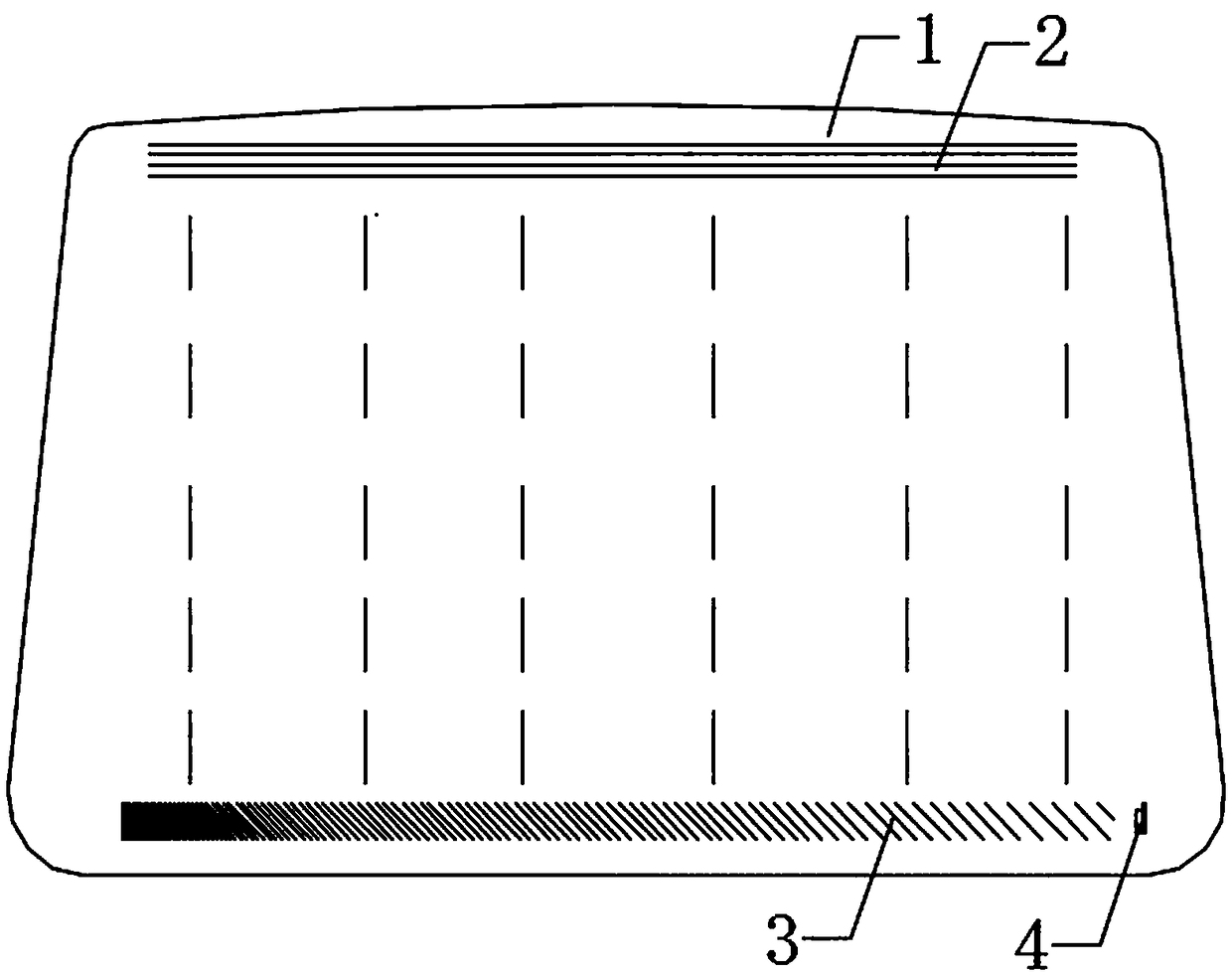
[0057] This embodiment discloses a method for detecting water mist on the inner surface of a windshield, which uses surface ultrasonic waves to detect the water mist on the inner surface 1 of the glass. Specifically, the detection method is as follows: the controller (not shown in the figure) controls the ultrasonic transceiver assembly to form a surface ultrasonic detection area on the inner surface 1 of the glass. When water mist is generated on the inner surface 1 of the glass, the The surface ultrasonic wave is absorbed and attenuated, and the controller determines the position of the water mist on the inner surface 1 of the glass according to the received attenuation signal.

[0058] In this embodiment, the frequency of the surface ultrasonic waves is set to 1.1-10 MHz, which is applicable to windshields of different thicknesses.

Embodiment 2

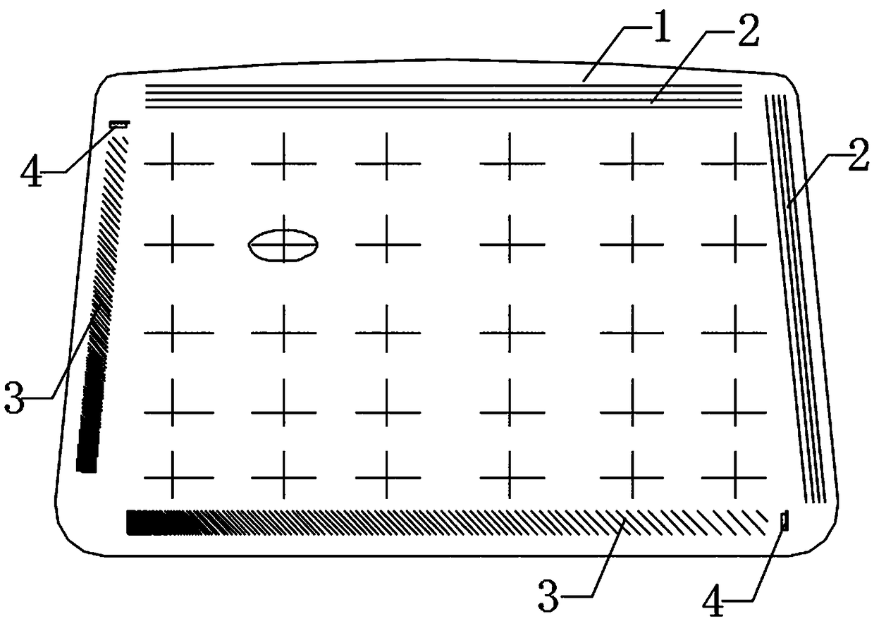
[0060] This embodiment discloses a method for detecting water mist on the inner surface of a windshield, which uses surface ultrasonic waves to detect the water mist on the inner surface 1 of the glass. Specifically, the detection method is as follows: the controller (not shown in the figure) controls the ultrasonic transceiver assembly to form a surface ultrasonic detection area on the inner surface 1 of the glass. When water mist is generated on the inner surface 1 of the glass, the The surface ultrasonic wave is absorbed and attenuated, and the controller determines the position of the water mist on the inner surface 1 of the glass according to the received attenuation signal.

[0061] In this embodiment, when the attenuation signal received by the controller is higher than the set value, it indicates that the amount of water mist on the inner surface 1 of the glass is relatively large, and it is determined that the amount of water mist on the inner surface 1 of the glass af...

Embodiment 3

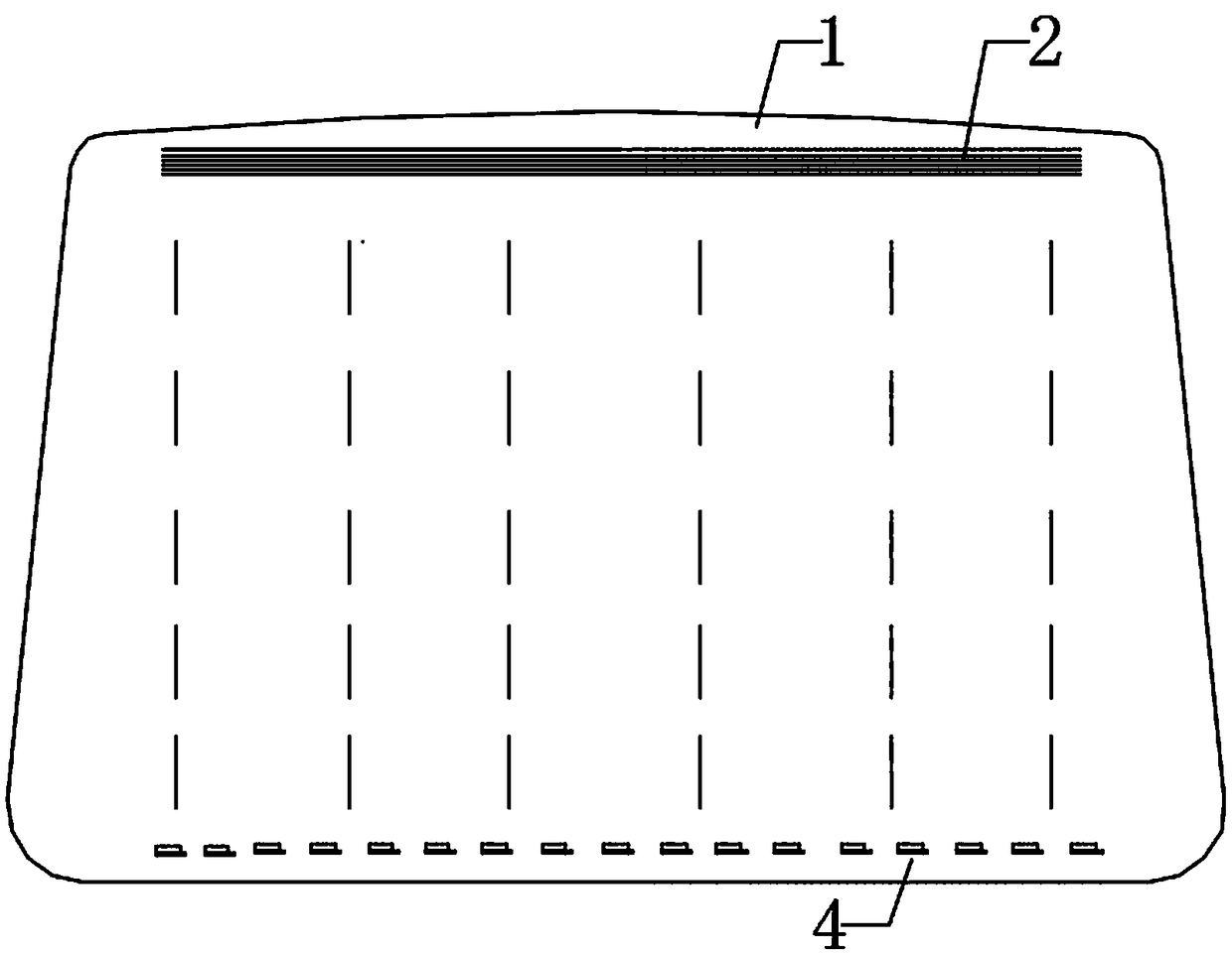
[0063] This embodiment discloses a method for detecting water mist on the inner surface of a windshield, which uses surface ultrasonic waves to detect the water mist on the inner surface 1 of the glass. Specifically, the detection method is as follows: the controller (not shown in the figure) controls the ultrasonic transceiver assembly to form a surface ultrasonic detection area on the inner surface 1 of the glass. When water mist is generated on the inner surface 1 of the glass, the The surface ultrasonic wave is absorbed and attenuated, and the controller determines the position of the water mist on the inner surface 1 of the glass according to the received attenuation signal.

[0064] In this embodiment, when the attenuation signal received by the controller is higher than the set value, it indicates that the amount of water mist on the inner surface 1 of the glass is relatively large, and it is determined that the amount of water mist on the inner surface 1 of the glass af...


PUM

PropertyMeasurementUnit
thicknessaaaaaaaaaa

Abstract

The invention discloses a method for detecting water mist on the inner surface of a windshield. The method mainly comprises the following steps of detecting water mist on the inner surface of the glass by utilizing surface ultrasonic waves. Water mist on the inner surface of the windshield can be accurately detected, and the specific position of a water mist area on the inner surface of the windshield can be recognized, so as to achieve the purpose of accurate defogging.

Description

technical field [0001] The invention relates to the field of automobile auxiliary technology, in particular to a method for detecting water mist on the inner surface of a windshield. Background technique [0002] In cold weather, it is easy to condense water mist on the windshield of the car, or when the humidity and temperature in the car are quite different from the external environment, the water mist is also easy to condense on the windshield of the car. When water mist condenses on the windshield, it will seriously affect the driver's sight and easily lead to safety accidents. Therefore, it is necessary to deal with the water mist on the windshield. [0003] At present, the observation, determination and removal of water mist on the windshield are usually controlled by the driver based on experience, that is, when the water mist area on the windshield spreads to a certain level, the driver removes the water mist by manually wiping or turning on the air conditioner . H...

Claims


Application Information

Patent Timeline
Patent Type & Authority Applications(China)
IPC IPC(8): G01N29/04G01N29/11G01N29/22
CPCG01N29/041G01N29/11G01N29/223G01N2291/015G01N2291/0232
Inventor 张萍郑伦见罗琳陈攀宇
Owner GENERAL TOUCH CO LTD
Why Eureka
Try Eureka