Supercharge Your Innovation With Domain-Expert AI Agents!

Ceiling cleaning device for construction

A technology for cleaning devices and ceilings, used in cleaning equipment, cleaning machinery, applications, etc., can solve the problems of excessive dust, low efficiency, asynchronous cleaning and water spraying, etc., and achieve the effect of improving the cleaning effect.

Inactive Publication Date: 2018-12-18
胡浩成
View PDF5 Cites 2 Cited by
  • Summary
  • Abstract
  • Description
  • Claims
  • Application Information

AI Technical Summary

Problems solved by technology

[0002] There is a lot of dust on the roof of a new building, and the cleaning of the ceiling is done manually on a ladder. It is very dangerous to work on the ladder, and the working time of cleaning the ceiling is long, the efficiency is low, and it cannot meet the construction progress of the project. Therefore, there is an urgent need for an automatic cleaning house building ceiling sweeping device
To clean the ceiling, corresponding clean water must be provided at the same time to assist the cleaning operation. However, when the equipment is cleaned, water is often sprayed at the same time as cleaning; often resulting in a situation where cleaning and water spraying are not synchronized, resulting in a lot of waste of clean water and often getting wet moreover, the single-time efficiency is not high, and multiple cleanings are often required; such a vicious circle increases the difficulty of personnel's work, and at the same time wastes more water.

Method used


Image

  • Ceiling cleaning device for construction
  • Ceiling cleaning device for construction
  • Ceiling cleaning device for construction

Examples


Embodiment 1

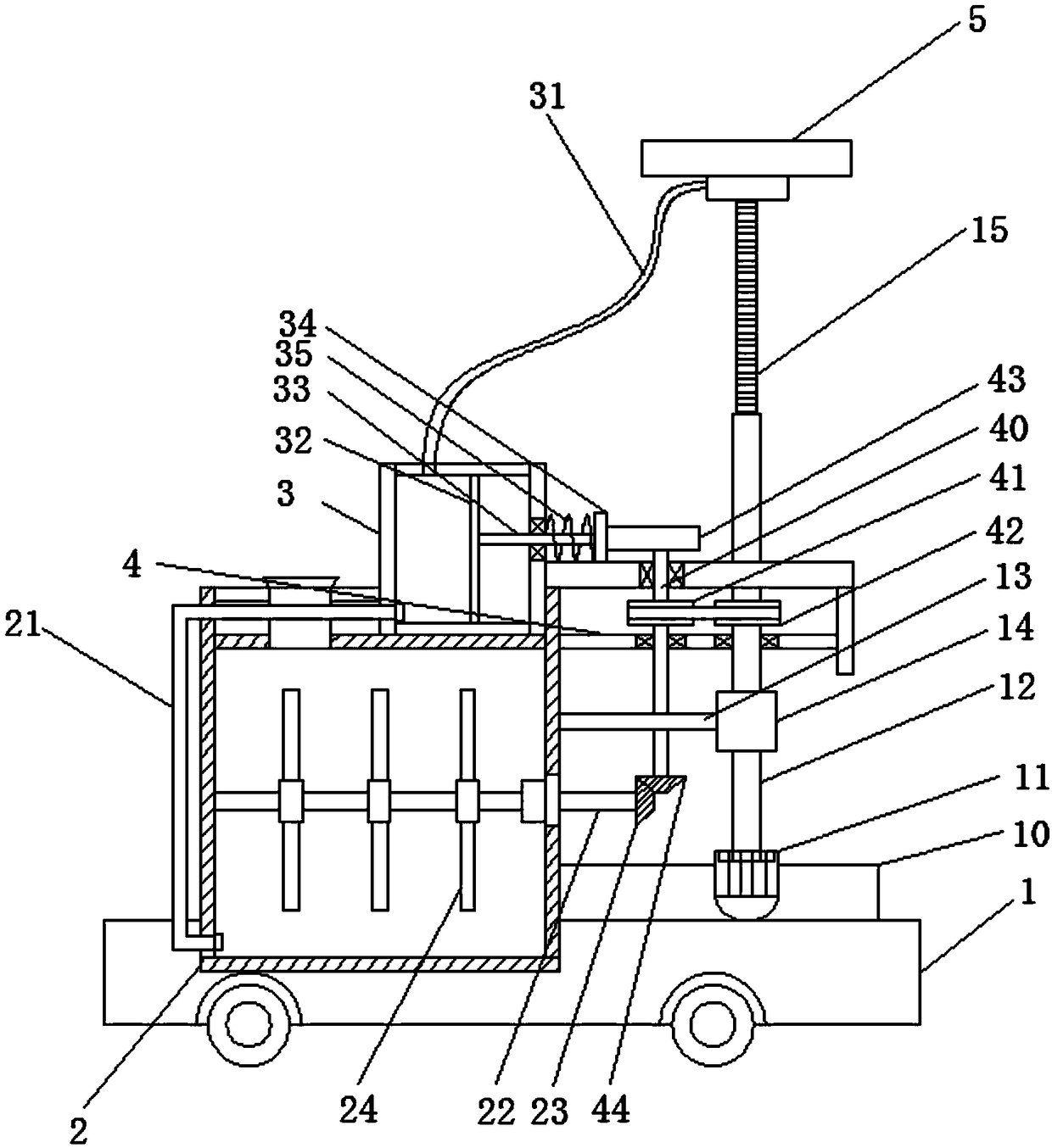
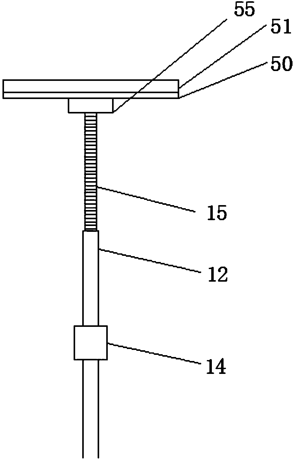
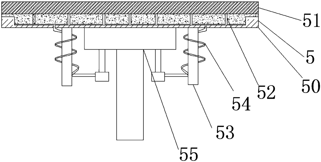
[0018] Example 1: Please refer to figure 2 with image 3 A fixing frame 13 is installed on the base 1, a fixing sleeve 14 is installed at the front end of the fixing frame 13, a transmission sleeve 12 is inserted into the fixing sleeve 14, and a base 10 is installed on the base 1, A drive motor 11 is installed on the base 10, the drive sleeve 12 is connected to the motor shaft of the drive motor 11 through a coupling, and a threaded rod 15 is penetrated in the drive sleeve 12, the threaded rod 15 external threads are provided on the outer wall, internal threads are provided on the inner wall of the transmission sleeve 12, the threaded rod 15 is engaged with the transmission sleeve 12 through threads, and a cleaning wipe 5 is installed on the top of the threaded rod 15, The cleaning wipe 5 is designed to have a disc-shaped structure. The cleaning wipe 5 includes a housing 20 and a wipe pad 51. The housing 20 is fixed on the bottom surface of the wipe pad 51. The bottom of the h...

Embodiment 2

[0021] Example 2: Please refer to figure 1 As a further solution of the first embodiment, the difference from the first embodiment is that a transmission shaft 40 is vertically installed on the frame 4, a transmission wheel 42 is installed on the transmission sleeve 12, and the transmission shaft 40 is A driven wheel 41 is installed, the driven wheel 41 and the transmission wheel 42 are connected by a belt, a cam 43 is installed at the top of the transmission shaft 40, a piston plate 32 is installed in the water delivery cylinder 3, and the piston plate 32 is connected with a piston rod 33. The front end of the piston rod 33 passes through the water delivery cylinder 3 and is equipped with a pressing plate 34 which is in contact with the cam 43. The front section of the piston rod 33 is wound with a reset A spring 35, one end of the return spring 35 is mounted on the pressing plate 34, and the other end of the return spring 35 is fixed on the front plane of the water delivery cy...

Embodiment 3

[0023] Example 3: Please refer to figure 1 As a further solution of the second embodiment, the difference from the second embodiment is that a stirring shaft 24 is installed horizontally in the water tank 2, and the stirring shaft 24 is installed horizontally to ensure the stirring range of the material at the bottom; the front end of the stirring shaft 24 A driven helical gear 23 is installed, a transmission helical gear 44 is installed at the bottom end of the transmission shaft 40, the transmission helical gear 44 meshes with the driven helical gear 23, and several pairs of stirring rods are installed on the stirring shaft 24 24. The stirring rod 24 is equidistantly installed on the stirring shaft 24, and the top of the water tank 2 is provided with a feeding port.

[0024] During operation, while the transmission shaft 40 rotates, the transmission helical gear 44 rotates synchronously, and the gear meshing transmission drives the stirring shaft 24 to rotate, thereby performing...


PUM


Abstract

The invention discloses a ceiling cleaning device for construction. The device comprises a base. The base is provided with a water tank, a water conveying cylinder and a frame, wherein the water tankis connected with the water conveying cylinder through a water conveying pipe. The base is provided with a fixing frame. The front end of the fixing frame is provided with a fixing sleeve. A transmission sleeve penetrates through the fixing sleeve. A threaded rod penetrates through the transmission sleeve. The top of the threaded rod is provided with a cleaning eraser. The cleaning eraser has a disc-shaped structure. The cleaning eraser comprises a housing and a wiping pad. A water conveying box is mounted on the bottom plane of the housing. A water outlet pipe is arranged between the water conveying box and the water conveying cylinder for connecting. The water conveying box is provided with a plurality of branched pipes. The wiping pad is provided with a plurality of water inlet holes. According to the ceiling cleaning device, clear water is directly injected into the cleaning eraser in cleaning the ceiling, thereby wetting the cleaning eraser. Not only are waste and dropping causedby a large amount of water prevented, but also a cleaning effect is greatly improved.

Description

Technical field [0001] The invention relates to the field of construction, in particular to a ceiling cleaning device for construction. Background technique [0002] There is a lot of dust on the roof of the new building, and the cleaning of the ceiling is manual climbing on the ladder. It is very dangerous to work on the ladder. Moreover, the cleaning of the ceiling takes a long time and the efficiency is low, which cannot meet the construction schedule. Therefore, an automatic Cleaning the ceiling sweeping device of house construction. When cleaning the ceiling, it is necessary to provide corresponding clean water to assist the cleaning operation. However, when the equipment is cleaned, it is often sprayed at the same time as the cleaning; it often results in a situation where the cleaning and the spray are not synchronized, which causes a lot of waste of clean water and often gets wet. In addition, the single-time efficiency is not high, and it often requires multiple cleanin...

Claims


Application Information

Patent Timeline
Patent Type & Authority Applications(China)
IPC IPC(8): A47L11/38A47L11/40
CPCA47L11/38A47L11/40A47L11/4036A47L11/4072A47L11/4083A47L11/4088
Inventor 胡浩成
Owner 胡浩成
Features
  • R&D
  • Intellectual Property
  • Life Sciences
  • Materials
  • Tech Scout
  • Unparalleled Data Quality
  • Higher Quality Content
  • 60% Fewer Hallucinations
Learn More