Supercharge Your Innovation With Domain-Expert AI Agents!

Ureteroscope

A technology of ureteroscope and mirror sheath, applied in the field of ureteroscope, can solve the problems of blocking water circulation, not being able to maintain a clear vision for a long time, bladder retention, etc., and achieve a balanced effect

Pending Publication Date: 2018-12-18
江苏柯汇医疗科技有限公司
View PDF0 Cites 2 Cited by
  • Summary
  • Abstract
  • Description
  • Claims
  • Application Information

AI Technical Summary

Problems solved by technology

[0002] The current ureteroscope has only one channel, and the water inlet and outlet are in the same cavity, so there are some problems as follows: First, when the water inlet and outlet valves of the ureteroscope are opened at the same time, the water pressure cannot be observed due to insufficient water pressure.
The water outlet valve must be closed; secondly, the field of vision is often unclear due to the inability of the water to circulate. Clinically, when the field of vision is unclear, a catheter should be inserted in the cavity to drain water, and then the catheter should be pulled out before operation. Circulation caused blurred vision, and it was necessary to insert a catheter in the cavity to drain water, which required repeated repetitions, and the continuous water injection caused the water pressure at the tip of the scope and the kidney to be too high; The opening is just physiologically narrow, which blocks the water circulation and cannot maintain a clear vision for a long time; at the same time, the ureteroscope can only maintain a clear vision when the water intake and drainage are balanced. Therefore, it is impossible to realize simultaneous water inflow and drainage
In addition, the existing ureteroscope cannot immediately discharge the water and urine in the patient's bladder. When the operation time is too long, the water pressure in the patient's bladder will gradually increase, resulting in the retention of water and urine in the bladder. It is necessary to pull out the ureteroscope to discharge the water in the bladder. , and then insert the ureteroscope, the operation process is more cumbersome

Method used


Image

  • Ureteroscope
  • Ureteroscope
  • Ureteroscope

Examples


Embodiment Construction

[0015] The present invention is described in further detail now in conjunction with accompanying drawing. These drawings are all simplified schematic diagrams, which only illustrate the basic structure of the present invention in a schematic manner, so they only show the configurations related to the present invention.

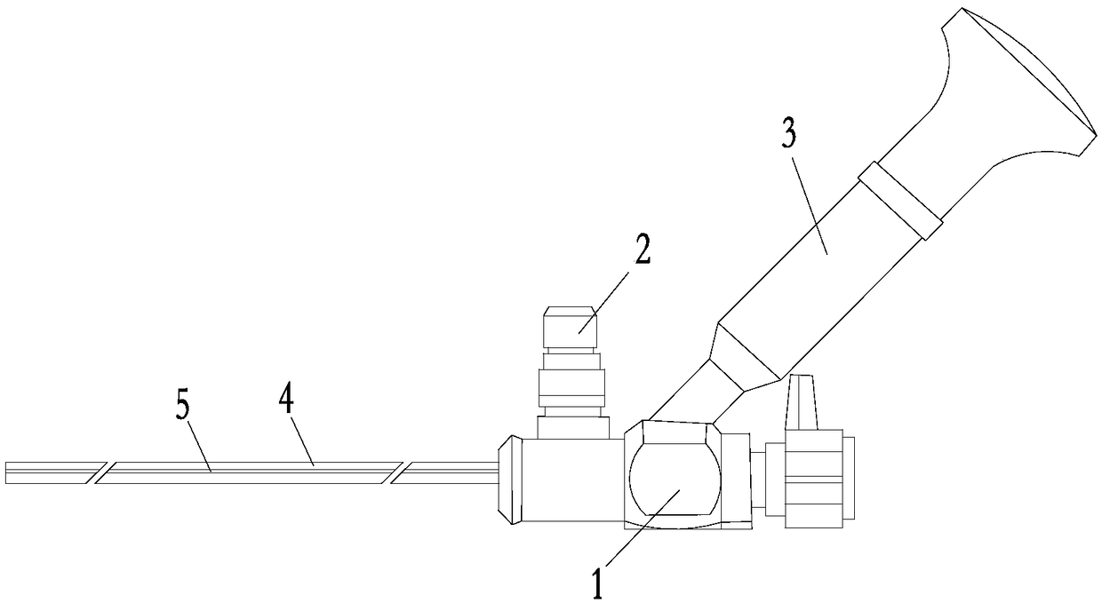
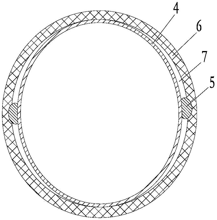
[0016] Such as Figure 1 ~ Figure 4 As shown, a ureteroscope includes a handle 1, a light source interface 2 and a camera eyepiece 3 are installed on the side of the handle 1, a mirror sheath 4 is connected to the front end of the handle 1, and the outer wall of the mirror sheath 4 is provided with two symmetrical mirror sheaths 4 Axial convex strips 5 arranged on the axis, the front end of the axial convex strips 5 starts from the front end of the mirror sheath 4, the rear end of the axial convex strips 5 is 10 cm away from the front end of the handle 1, and the axial convex strips 5 make the inner wall of the ureter 6 The gap with the outer wall of the mirr...


PUM


Abstract

The invention relates to a ureteroscope, which has a handle. A light source interface and a camera eyepiece are mounted on a side of the handle, the front end of the handle is connected with a mirrorsheath, and an outer wall of the mirror sheath is provided with an axial rib, and the axial rib makes a gap between the inner wall of a ureter and the outer wall of the mirror sheath to form a drainage channel during a surgery. An axial rib on the outer wall of the mirror sheath, so that the gap between the inner wall of the ureter and the outer wall of the mirror sheath forms a drainage channel,so that water inlets from the mirror sheath and discharged from the drainage channel, thereby realizing the balance of inlet water and discharged water. The shape of the mirror sheath can be changed to meet the displacement requirement, thereby realizing the purpose of maintaining a clear vision and reducing the water pressure in a kidney. A bladder guide can be used in cooperation, convenient detachability is ensured, drainage of water and urine in the bladder in an uninterrupted surgery is achieved.

Description

technical field [0001] The invention relates to the technical field of medical instruments, in particular to a ureteroscope. Background technique [0002] The current ureteroscope has only one channel, and the water inlet and outlet are in the same cavity, so there are some problems as follows: First, although the water inlet and outlet valve of the ureteroscope is opened at the same time, the water pressure cannot be observed due to insufficient water pressure. The water outlet valve must be closed; secondly, the field of vision is often unclear due to the inability of the water to circulate. Clinically, when the field of vision is unclear, a catheter should be inserted in the cavity to drain water, and then the catheter should be pulled out before operation. Circulation caused blurred vision, and it was necessary to insert a catheter in the cavity to drain water, which required repeated repetitions, and the continuous water injection caused the water pressure at the tip of...

Claims


Application Information

Patent Timeline
IPC IPC(8): A61B1/307A61B1/015
CPCA61B1/015A61B1/307
Inventor 杨润学林超
Owner 江苏柯汇医疗科技有限公司
Features
  • R&D
  • Intellectual Property
  • Life Sciences
  • Materials
  • Tech Scout
  • Unparalleled Data Quality
  • Higher Quality Content
  • 60% Fewer Hallucinations
Learn More