Pipe cutting machine tool

A technology for cutting pipes and machine tools, applied in the field of mechanical devices, can solve problems such as large errors and large workload, and achieve the effects of convenient transportation, reduced workload, and improved work efficiency

Active Publication Date: 2018-12-18
HEFEI YAOSHI TONGHUI TECH CO LTD
View PDF4 Cites 0 Cited by
  • Summary
  • Abstract
  • Description
  • Claims
  • Application Information

AI Technical Summary

Problems solved by technology

The traditional pipe cutting is to measure the length with a tape measure first, mark it with a marker pen, and then use a cutting machine to cut the pipe, and each time you cut the pipe, you need to use the tape measure again to measure the distance and make marks. The workload is relatively large. For the problem that the error of cutting at the mark is relatively large

Method used


Image

  • Pipe cutting machine tool
  • Pipe cutting machine tool
  • Pipe cutting machine tool

Examples


Embodiment Construction

[0018] In order to make the technical means, creative features, goals and effects achieved by the present invention easy to understand, the present invention will be further described below in conjunction with specific embodiments.

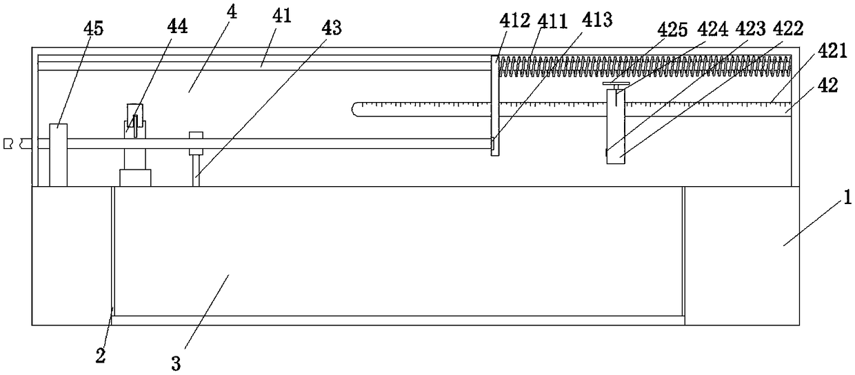
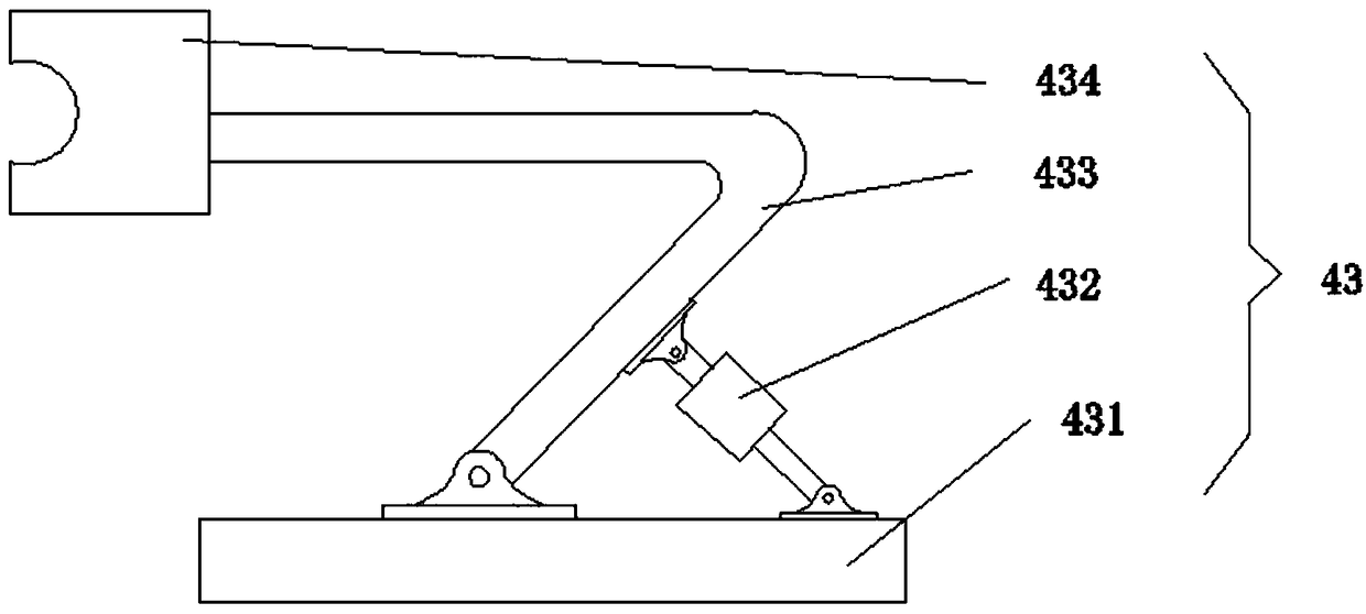
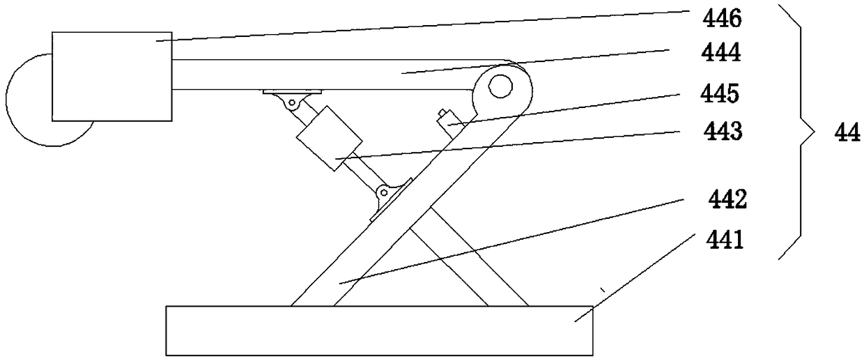
[0019] Such as Figure 1-4 As shown, a pipe cutting machine tool includes a machine base 1, the front of the machine base 1 is provided with a feeding trough 2 at the middle position near the bottom of the machine base 1, and the inner surface of the feeding chute 2 is provided with a storage box 3, and the front of the machine base 1 A working room 4 is arranged at the position above the material box 3 .

[0020] A pipe cutting machine tool of the present invention, by sliding the scale 421 on the benchmark rod 42, adjusting the proper position of the positioning seat 422 and the pipe cutting machine 446, then fixing the positioning seat 422, pushing the pipe so that one end of it is inserted into the upper pipe of the limit pipe seat 421 Fittin...


PUM


Abstract

The invention discloses a pipe cutting machine tool which comprises an engine base. A feeding groove is formed in the middle, close to the bottom of the engine base, of the front face of the engine base; a containing box is arranged on the inner surface of the feeding groove; and a working room is arranged on the position, above the containing box, of the front face of the engine base. By observing a scale on a sliding marker rod, the appropriate positions of a positioning seat and a pipe cutting machine are adjusted; through the scale on the sliding marker rod, an operator can conveniently determine the length of a pipe needing to be cut, and after the positioning seat is fixed, the cutting position does not need to be determined for cutting every time; the pipe is pushed, and one end ofthe pipe is embedded into a pipe coincidence groove in a limiting pipe seat; under the effect of thrust, the limiting pipe seat moves towards the positioning seat and touches a pipe cutting telescopicair cylinder control switch on the positioning seat, and the pipe cutting telescopic air cylinder control switch controls a pipe cutting telescopic air cylinder to retract so as to enable the pipe cutting machine to cut the pipe; and after cutting is completed, a pipe cutting rod arm touches a stripping telescopic air cylinder control switch, a stripping telescopic air cylinder extends, and thusa pipe limiting block pushes the pipe to enter the containing box.

Description

technical field [0001] The invention relates to the field of mechanical devices. Background technique [0002] At present, the pipe cutting machine tool is a kind of machine tool equipment commonly used in industrial production, which can cut pipes. The traditional pipe cutting is to measure the length with a tape measure first, mark it with a marker pen, and then use a cutting machine to cut the pipe, and each time you cut the pipe, you need to use the tape measure again to measure the distance and make marks. The workload is relatively large. For the problem that the error of cutting at the mark is relatively large. Contents of the invention [0003] The main purpose of the present invention is to provide a pipe cutting machine tool. By sliding the scale on the pole, the proper position of the positioning seat and the pipe cutting machine is adjusted, and then the positioning seat is fixed, and the pipe is pushed so that one end of it is embedded in the limit pipe seat ...

Claims


Application Information

Patent Timeline
IPC IPC(8): B23D21/00B23D33/02B23D33/12B23Q7/00B23Q7/06B23Q7/10
Inventor 顾运辉顾明东
Owner HEFEI YAOSHI TONGHUI TECH CO LTD
Why Eureka
Try Eureka