Pipeline welding method suitable for compressor and lubrication oil station matched with compressor for use
A welding method and lubricating oil technology, applied in the field of compressor manufacturing, can solve the problems of processing quality, prolong the manufacturing cycle, increase the production cost, etc., and achieve the effects of improving the welding quality, reducing the shrinkage and reducing the filling.
- Summary
- Abstract
- Description
- Claims
- Application Information
AI Technical Summary
Problems solved by technology
Method used
Image
Examples
Embodiment 1
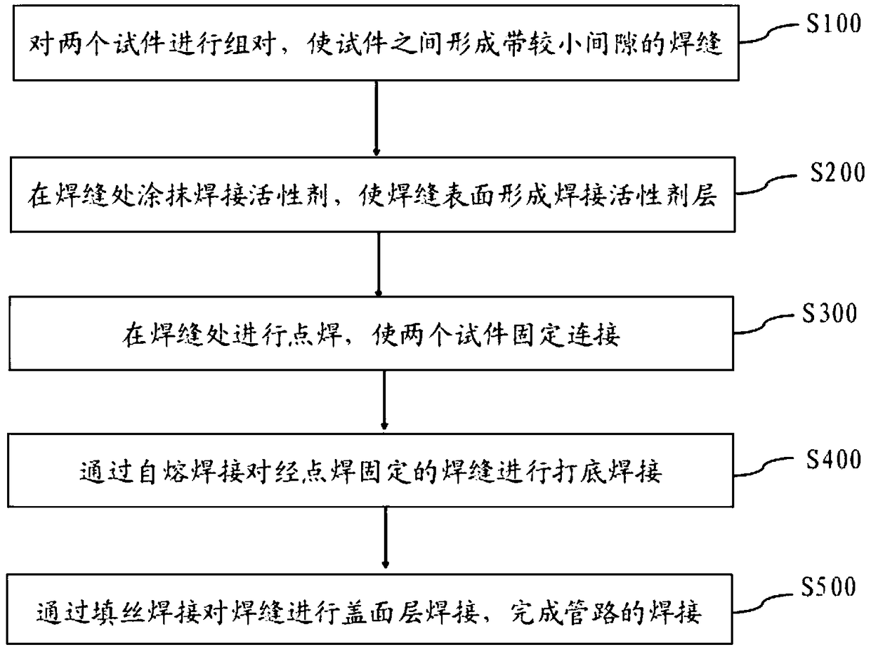
[0038] Such as figure 1 As shown, a pipeline welding method suitable for the compressor and its supporting lubricating oil station, including:
[0039] S100. Assembling two pipeline test pieces to be welded with a thickness less than 8 mm, so that a weld with a gap of 0-2 mm is formed between the two test pieces;
[0040] S200, apply a welding activator at the weld between the two test pieces, so that the surface of the weld forms a welding activator layer with a thickness of 35um, and the width of the welding activator layer formed on both sides of the weld is 8mm; Wherein, the welding activator includes the following components in parts by weight: CaF 2 20%, CrC1 3 10%, KF 13%, MgCl 2 38%;
[0041] S300, spot welding is performed at the weld seam where the welding activator layer is formed on the surface, so that the two test pieces are fixedly connected;
[0042] S400. Carry out root welding to the weld fixed by spot welding by means of self-fluxing welding; wherein, t...
Embodiment 2
[0045] Such as figure 1 As shown, a pipeline welding method suitable for the compressor and its supporting lubricating oil station, including:
[0046] S100. Assembling two pipeline test pieces to be welded with a thickness less than 8 mm, so that a weld with a gap of 0-2 mm is formed between the two test pieces;
[0047] S200, apply a welding activator on the weld between the two test pieces, so that the surface of the weld forms a welding activator layer with a thickness of 45um, and the width of the welding activator layer formed on both sides of the weld is 10mm; Wherein, the welding activator includes the following components in parts by weight: CaF 2 22%, CrC1 3 12%, KF 15%, MgCl 2 40%;
[0048] S300, spot welding is performed at the weld seam where the welding activator layer is formed on the surface, so that the two test pieces are fixedly connected;
[0049] S400. Carry out root welding to the weld fixed by spot welding by self-fluxing welding; wherein, the weldi...
Embodiment 3
[0052] Such as figure 1 As shown, a pipeline welding method suitable for the compressor and its supporting lubricating oil station, including:
[0053] S100. Assembling two pipeline test pieces to be welded with a thickness less than 8 mm, so that a weld with a gap of 0-2 mm is formed between the two test pieces;
[0054] S200, apply a welding activator at the weld between the two test pieces, so that the surface of the weld forms a welding activator layer with a thickness of 50um, and the width of the welding activator layer formed on both sides of the weld is 12mm; Wherein, the welding activator includes the following components in parts by weight: CaF 2 24%, CrC1 3 14%, KF 17%, MgCl 2 42%;
[0055] S300, spot welding is performed at the weld seam where the welding activator layer is formed on the surface, so that the two test pieces are fixedly connected;
[0056] S400. Carry out root welding to the weld fixed by spot welding by self-fluxing welding; wherein, the weldi...
PUM
| Property | Measurement | Unit |
|---|---|---|
| width | aaaaa | aaaaa |
| thickness | aaaaa | aaaaa |
| width | aaaaa | aaaaa |
Abstract
Description
Claims
Application Information
 - R&D
- Intellectual Property
- Life Sciences
- Materials
- Tech Scout
- Unparalleled Data Quality
- Higher Quality Content
- 60% Fewer Hallucinations
Browse by: Latest US Patents, China's latest patents, Technical Efficacy Thesaurus, Application Domain, Technology Topic, Popular Technical Reports.
© 2025 PatSnap. All rights reserved.Legal|Privacy policy|Modern Slavery Act Transparency Statement|Sitemap|About US| Contact US: help@patsnap.com


