Method for quickly keeping heat displacement of spindle constant

A thermal displacement and spindle technology, which is applied in metal processing mechanical parts, maintenance and safety accessories, metal processing equipment, etc., can solve the problems of long time required, reduced machine tool processing efficiency, long time required for constant thermal displacement, etc., to achieve The effect of ensuring high-precision operation and improving the machining efficiency of machine tools

Active Publication Date: 2018-12-18
昆山市玉山镇新光威精密机械厂
View PDF7 Cites 3 Cited by
  • Summary
  • Abstract
  • Description
  • Claims
  • Application Information

AI Technical Summary

Problems solved by technology

At present, the machine tool generally adopts the method of uninterrupted forced circulation of the cooling medium with a set temperature (such as 23-25 ​​degrees) to cool the electric spindle, that is, the cooling medium cooled by the cooling device is forcibly circulated into the spindle to take away the spindle. The heat generated by high-speed rotation, but this cooling method has the technical problem that it takes too long for the thermal displacement to be constant, especially when the spindle changes from a high-heating working state to a low-heating working state, or from a low-heating working state. When the state is changed to a high-calorie working state, it takes longer for the thermal displacement to remain constant, which greatly reduces the machining efficiency of the machine tool

Method used

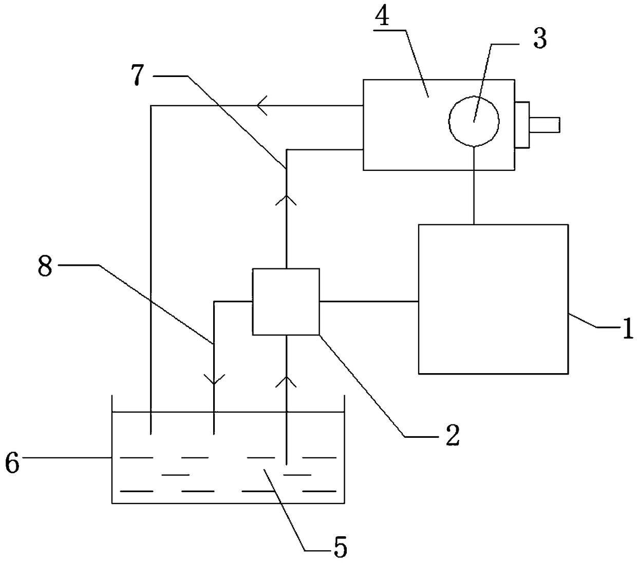

Image

  • Method for quickly keeping heat displacement of spindle constant

Examples


Embodiment 1

[0035] This embodiment is aimed at the situation that each working state of the spindle can be cooled to the temperature setting value A degree (such as 25 degrees) by the cooling medium with a set temperature (such as a lower temperature of 5 degrees). In this case, the cooling system quickly stabilizes the thermal displacement of the spindle as follows:

[0036] a. In each working state of the spindle, the cooling medium with a set temperature (such as 5 degrees) can cool the spindle to the temperature setting value A degree (such as 25 degrees):

[0037] a1. When the spindle is started in a certain working state (such as S3000 rpm), if the temperature of the spindle is less than or equal to the temperature setting value A degree (such as 25 degrees), the control system will issue an instruction to make the spindle stop cooling state.

[0038] a2. When the main shaft is running after step a1 or when the main shaft starts and runs in a certain working state (such as S1000 ro...

Embodiment 2

[0044] This embodiment aims at the situation that the cooling medium at a lower temperature (such as 5 degrees) cannot be cooled to the temperature setting value A degrees (such as 25 degrees) in each working state of the spindle. In this case, the cooling system quickly stabilizes the thermal displacement of the spindle as follows:

[0045] b. In each working state of the main shaft, the cooling medium with a set temperature (such as 5 degrees) cannot cool the main shaft to the temperature setting value A degree, pre-set the main shaft in each working state in the control system The corresponding target constant temperature X degrees, that is, the target constant temperature X degrees corresponding to each fixed value rotation speed of the spindle is set in the control system in advance:

[0046] b1. When the spindle is started in a certain working state (such as S9000 rpm), if the temperature of the spindle is lower than the target constant temperature X degree (such as 30 d...

Embodiment 3

[0055] This embodiment is aimed at the situation that the spindle cannot be cooled to the temperature setting value A by setting the cooling medium at a lower temperature (such as 5 degrees) in some working states of the spindle (for example, the same temperature of the spindle and the ambient temperature is 25 degrees). In this case, the cooling system quickly stabilizes the thermal displacement of the spindle as follows:

[0056] c. Set the temperature of the cooling medium (such as 5 degrees) to be constant, and the cooling medium at the set temperature (such as 5 degrees) cannot cool the spindle to the temperature setting value A degrees in part of the working state of the spindle (such as a fixed value speed). (For example, 25 degrees), in the control system, set the fixed value speed of the spindle and the corresponding target constant temperature:

[0057] c1. If the main shaft is working in a state where the cooling medium at a set temperature (such as 5 degrees) can c...


PUM


Abstract

The invention discloses a method for quickly keeping the heat displacement of a spindle constant. The method comprises the following steps that through a temperature sensor, the temperature of the spindle is detected and a temperature signal is output to a control system; through the control system, an electromagnetic valve is controlled to act according to the temperature signal, so that the spindle is in the circulating cooling state or the cooling stop state; furthermore, the rotating speed of the spindle is changed through the control system, so that the auxiliary cooling operation at a lower rotating speed can be achieved when the spindle is cooled; the cooling operation can be stopped when the spindle is heated, and the auxiliary heating operation at a higher rotating speed can be achieved; and the cooling operation is stopped from continuing when the spindle is shut down, the long-time temperature constancy is kept, and the auxiliary heating of the spindle is achieved, so that under the circumstance that the structure of the spindle is kept unchanged, the temperature variations of the spindle can be quickly and effectively controlled before the spindle is started up, duringthe running process of the spindle, and after the spindle is stopped, no extra time for waiting for the heat displacement of the spindle is needed, the heat displacement of the spindle can be stabilized and kept constant for a long time within a shorter time, the high-precision running of the spindle can be ensured, and the processing efficiency of a machine tool can be greatly improved.

Description

technical field [0001] The invention relates to the technical field of thermal displacement of a machine tool spindle, in particular to a method for fast and constant thermal displacement of a spindle. Background technique [0002] The electric spindle is a new technology in the field of CNC machine tools that integrates the machine tool spindle and the spindle motor. Together with the linear motor technology and high-speed tool technology, it pushes high-speed machining into a new era. The electric spindle is usually composed of a shellless motor, a spindle, a bearing, a spindle unit housing, a drive module, and a cooling device. The rotor of the motor is integrated with the main shaft by press-fitting method, and the main shaft is supported by front and rear bearings. The stator of the motor is installed in the housing of the main shaft unit through the cooling sleeve. The speed change of the spindle is controlled by the spindle drive module, and the temperature rise in ...

Claims


Application Information

Patent Timeline
Patent Type & Authority Applications(China)
IPC IPC(8): B23Q11/14
CPCB23Q11/14
Inventor 贾金铎
Owner 昆山市玉山镇新光威精密机械厂
Why Eureka
Try Eureka