A die-cutting mold for automotive interior parts

A technology for automotive interior parts and forming molds, which is applied to household appliances, household components, and other household appliances. It can solve the problems of slow production speed, high labor cost, and long production cycle, so as to improve work efficiency and achieve good molding effects. Effect

Active Publication Date: 2021-01-05
扬州双集机械有限公司
View PDF9 Cites 0 Cited by
  • Summary
  • Abstract
  • Description
  • Claims
  • Application Information

AI Technical Summary

Problems solved by technology

[0003] The object of the present invention is to provide a punching mold for automotive interior parts, through which a heating chamber and a heating plate are provided, the hot-melted molding raw material is extruded into the mold cavity through the injection screw, and then the hydraulic lifting rod works to drive the top plate Lower, put the heating plate close to the raw material in the mold cavity, the heating plate and the heating coil in the heating cavity work, respectively heat the raw material in the mold from the top and bottom, and make the raw material rapid prototyping through all-round thermoplastic molding , improve work efficiency, in order to solve the problem that the outer side of the mold is used to heat the mold to shape the jewelry, the production efficiency is low, the production speed is slow, the production cycle is long, and the labor cost is high.

Method used


Image

  • A die-cutting mold for automotive interior parts
  • A die-cutting mold for automotive interior parts
  • A die-cutting mold for automotive interior parts

Examples


Embodiment 1

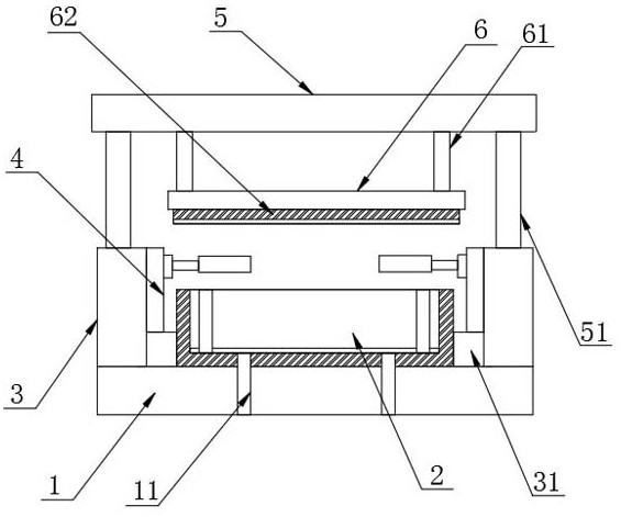
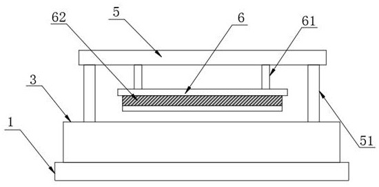
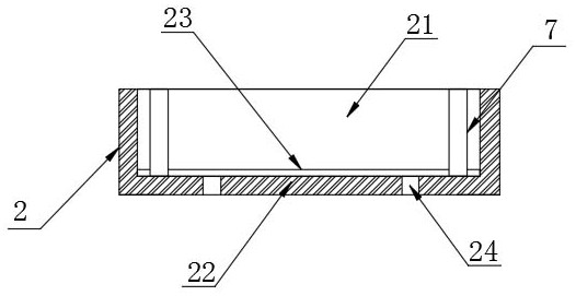
[0022] The present invention provides such Figure 1-5 A punching and forming die for automotive interior parts shown includes a base 1, a mold base 2 is provided on the top of the base 1, a mold cavity 21 is provided inside the mold base 2, and a mold cavity 21 is arranged around the outside of the mold base 1. There is a heating chamber 22, support blocks 3 are provided on both sides of the mold base 2, a punching device 4 is provided on the inner side of the support block 3, a top plate 5 is provided on the top of the mold base 2, and a top plate 5 is provided on the bottom of the top plate 5. Lifting plate 6, a fixed rod 61 is evenly arranged between the lifting plate 6 and the top plate 5, and a heating plate 62 is arranged at the bottom of the fixing rod 61, and the inside of the heating chamber 22 and the heating plate 62 are filled with heating coils.

[0023] Beneficial effects of this embodiment:

[0024] The hot-melted molding raw material is extruded into the mold...

Embodiment 2

[0026] A cavity bottom plate 23 is provided at the bottom of the inner wall of the cavity 21 , and a communication hole 24 is formed inside the heating cavity 22 , and the communication hole 24 communicates with the cavity bottom plate 23 .

[0027] The base 1 is provided with a first electric push rod 11 inside, and the first electric push rod 11 penetrates through the heating chamber 22 and is fixedly connected with the mold cavity bottom plate 23 through a communication hole 24 .

[0028] Beneficial effects of this embodiment: After the decorative parts in the mold 21 are formed, the first electric push rod 11 can work to support the bottom plate 23 of the mold cavity, thereby ejecting the decorative parts on the top of the bottom plate 23 of the mold cavity, which is convenient for the decorative parts For processing and removal, improve work efficiency.

Embodiment 3

[0030] A limit block 31 is provided between the support block 3 and the mold base 2 , and a hydraulic lifting rod 51 is evenly provided between the top plate 5 and the support block 3 .

[0031] The punching device 4 includes a slide plate 41, a side plate 42, a slide block 43, a second electric push rod 44, a moving plate 45, a third electric push rod 46 and a cutting tool 47, and the slide plate 41 is arranged on the mold base 2 and Between the support blocks 3, the front side and the rear side of the slide plate 41 are provided with side plates 42, the surface of the side plate 42 is provided with a slider 43, and the slide block 43 is slidably connected with the slide plate 41, and the slide block 43 A second electric push rod 44 is arranged between the side plate 42, a moving plate 45 is arranged on the outside of the slider 43, a third electric push rod 46 is arranged between the moving plate 45 and the slider 43, and the moving A cutting tool 47 is attached to the outsi...


PUM

PropertyMeasurementUnit
thicknessaaaaaaaaaa

Abstract

The invention discloses an automobile interior trim part punching forming die. The automobile interior trim part punching forming die comprises a base with the top provided with a die base. A die cavity is formed in the die base. A heating cavity surrounds the outer side of the die cavity. Supporting blocks are arranged on the two sides of the die base. Punching devices are arranged on the inner sides of the supporting blocks. A top plate is arranged on the top of the die base. A lifting plate is arranged at the bottom of the top plate. Fixing rods are evenly arranged between the lifting plateand the top plate. A heating plate is arranged at the bottoms of the fixing rods. The interiors of the heating cavity and the heating plate are filled with heating coils. Through the arrangement of the heating cavity and the heating plate, formed raw materials obtained after hot melting are extruded to enter the die cavity through an injection molding screw, then, hydraulic lifting rods work anddrive the top plate to descend, the heating plate is closely attached to the raw materials in the die cavity, and the heating coils in the heating plate and the heating cavity work and heat the raw materials in the die from the top and the bottom; and through all-direction thermoplastic forming work, the raw materials are rapidly formed, and the work efficiency is improved.

Description

technical field [0001] The invention relates to the field of moulds, in particular to a die for punching and forming automotive interior parts. Background technique [0002] With the increasing calls for environmental protection and energy saving in the international environment, and in order to cope with the urgent global warming and energy crisis, automobile lightweight technology has become one of the reliable ways to effectively alleviate the energy and climate crisis in the short term. The so-called automobile lightweight technology refers to the energy-saving design and improvement of each assembly and parts of the automobile under the premise of ensuring the basic performance of the automobile, so as to reduce the quality of the overall equipment of the automobile, thereby improving the power performance of the automobile and reducing fuel consumption. and exhaust pollution. Existing automotive interior and exterior parts products: such as wheel fenders, engine botto...

Claims


Application Information

Patent Timeline
Patent Type & Authority Patents(China)
IPC IPC(8): B29C45/00B29C45/26B29C45/40B29C45/73B26F1/44B29L31/58
CPCB26F1/44B29C45/0055B29C45/2602B29C45/401B29C45/73B29C2045/0058B29L2031/58
Inventor 陈宇
Owner 扬州双集机械有限公司
Why Eureka
Try Eureka