Product housing sleeve equipment

A technology of casing and equipment, which is applied in the directions of paper/cardboard containers, container manufacturing machinery, box making operations, etc., can solve the problems of crooked holes, inconvenient adjustment of the rotation direction of the drill bit, disassembly and assembly, affecting the production and processing efficiency of packaging boxes, etc. Achieve the effect of preventing deviation, improving drilling efficiency and stability

Inactive Publication Date: 2018-12-18
广州市科卡通信科技有限公司
View PDF0 Cites 0 Cited by
  • Summary
  • Abstract
  • Description
  • Claims
  • Application Information

AI Technical Summary

Problems solved by technology

[0002] In the production and processing of packaging boxes, the punching work of traditional packaging boxes mainly relies on the workers to hold the punching machine for manual punching. Although this is greatly conducive to the convenient and quick punching operation, the problem is that the In the process of manual punching, because only manual experience is used to align the drill bit to the packaging box, people's hands are prone to shake when punching holes, so it is easy to punch the hole crookedly, which greatly affects the quality of packaging box preparation and The preparation speed, and the traditional drilling equipment is inconvenient to adjust the rotation direction and disassembly of the drill bit. Therefore, the drilling has strong limitations and is inconvenient to use, which affects the production and processing efficiency of the packaging box. It needs to be improved.

Method used


Image

  • Product housing sleeve equipment
  • Product housing sleeve equipment
  • Product housing sleeve equipment

Examples


Embodiment Construction

[0015] Combine below Figure 1-4 The present invention will be described in detail.

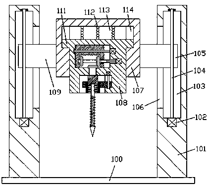
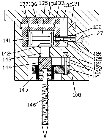
[0016] refer to Figure 1-4 , according to an embodiment of the present invention, a product casing device includes a base frame 100, a vertical frame 101 is fixed symmetrically on the top end of the base frame 100, and a casing is arranged between the vertical frames 101 on the left and right sides 107, the bottom end surface of the shell 107 is provided with a first chute 113, the first chute 113 is slidably fitted with a card mounting seat 108, and the top surface of the card mounting seat 108 is in contact with the first chute 113 A buffer elastic bar 112 is installed between the top walls, and a first groove 145 is provided in the bottom end surface of the mounting seat 108, and a first groove 145 is provided in the mounting seat 108 on the upper side of the first groove 145. The first transmission cavity 132, the part between the first groove 145 and the first transmission cavity 132 ...


PUM


Abstract

The invention discloses product housing sleeve equipment. The product housing sleeve equipment comprises a base frame, wherein vertical frames are symmetrically and fixedly arranged on the top end surface of the base frame left and right; a housing is arranged between the vertical frames at left and right sides; a first slide slot is formed in the bottom end surface of the housing; a clamping baseis mounted in the first slide slot in a sliding fit mode; a buffer elastic strip is mounted between the top end surface of the clamping base and the top wall of the first slide slot in a jacking-pressing matched mode; a first groove is formed in the bottom end surface of the clamping base; a first transmission cavity is arranged in the clamping base at the upper side of the first groove; the portion, between the first groove and the first transmission cavity, is rotatably equipped with a first rotary rod; the tail end of the top of the first rotary rod is fixedly equipped with a first conicalangle wheel; the tail end of the bottom of the first rotary rod is fixedly equipped with a clamping block; and an insertion slot is formed in the bottom end surface of the clamping block.

Description

technical field [0001] The invention relates to the technical field of packaging box processing, in particular to a product casing device. Background technique [0002] In the production and processing of packaging boxes, the punching work of traditional packaging boxes mainly relies on the workers to hold the punching machine for manual punching. Although this is greatly conducive to the convenient and quick punching operation, the problem is that the In the process of manual punching, because only manual experience is used to align the drill bit to the packaging box, people's hands are prone to shake when punching holes, which will easily make the hole crooked, which greatly affects the quality of packaging box preparation and The preparation speed, and the traditional drilling equipment is not convenient to adjust the rotation direction and disassembly of the drill bit. Therefore, the drilling has strong limitations and is inconvenient to use, which affects the production...

Claims


Application Information

Patent Timeline
Patent Type & Authority Applications(China)
IPC IPC(8): B31B50/14
CPCB31B50/14
Inventor 时建华
Owner 广州市科卡通信科技有限公司
Why Eureka
Try Eureka