High-transmission-efficiency cable winding device and method

A technology of transmission efficiency and gear transmission, which is applied in the field of cable take-up, can solve the problems of uncompact structure, large floor space and low transmission efficiency of the cable take-up device, and achieve the effect of compact structure design, small floor space and reliable movement

Pending Publication Date: 2018-12-18
马鞍山市方正机械制造有限责任公司
View PDF12 Cites 10 Cited by
  • Summary
  • Abstract
  • Description
  • Claims
  • Application Information

AI Technical Summary

Problems solved by technology

[0007] The purpose of the present invention is to overcome the disadvantages of uncompact structure, large floor space and low transmission efficiency of the prior art cable receiving device, and provide a high transmission efficiency cable receiving device and cable receiving method. The present invention adopts power split transmi...

Method used


Image

  • High-transmission-efficiency cable winding device and method
  • High-transmission-efficiency cable winding device and method
  • High-transmission-efficiency cable winding device and method

Examples


Embodiment 1

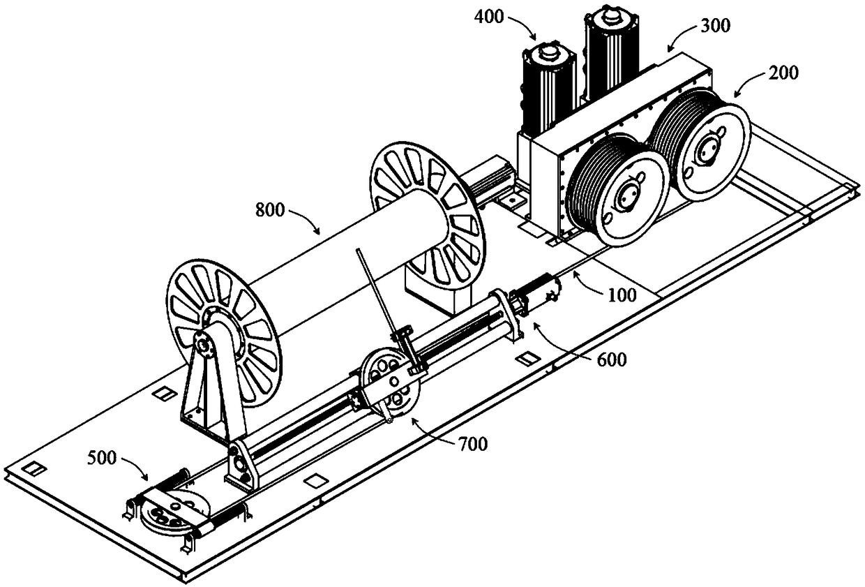
[0043] combine figure 1 , a cable receiving device with high transmission efficiency in this embodiment, comprising a cable 100, a traction reel 200, a gear transmission unit 300, a reel drive motor 400, a redirection unit 500, a cable discharge unit 700 and a cable storage unit 800, the The above-mentioned gear transmission unit 300 is arranged between the traction reel 200 and the reel drive motor 400, and the traction reel 200 and the reel drive motor 400 are both provided with two, and the two vertically arranged reel drive motors 400 pass through the gear The transmission unit 300 controls the rotation of the traction reel 200. When the external cable 100 enters the cable take-up device, the cable 100 is wound on the traction reel 200 at first, and the cable 100 is output through the traction reel 200. After being redirected by the redirection unit 500, the The cable discharge unit 700 winds the cable 100 on the cable storage unit 800 .

[0044] In this embodiment, when ...

Embodiment 2

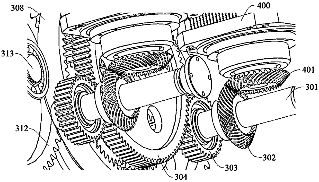
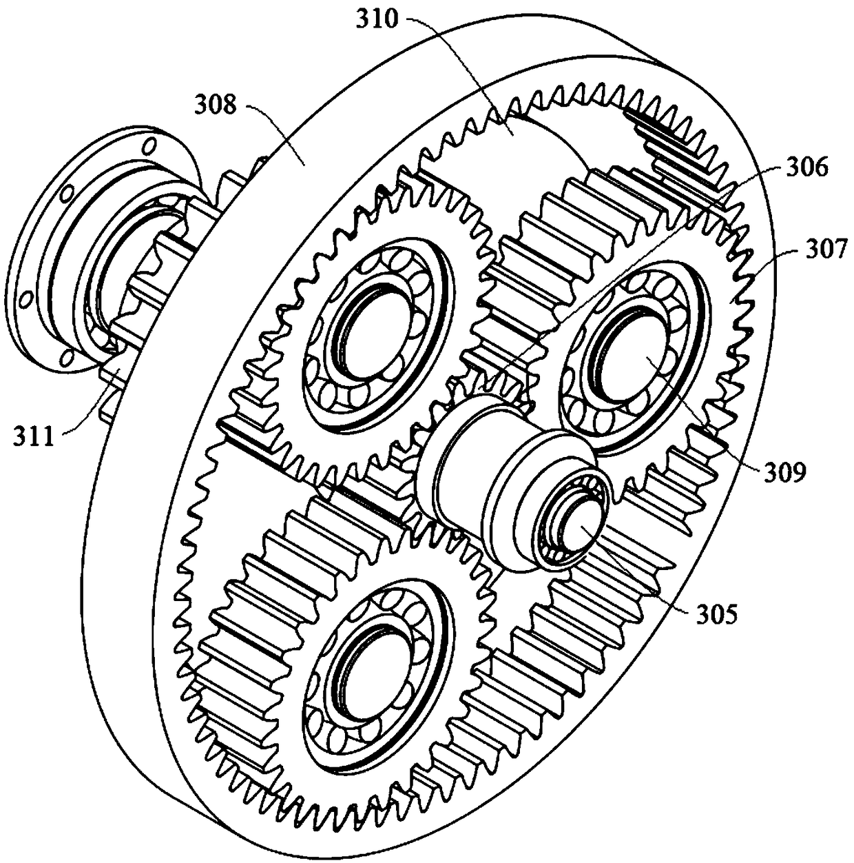
[0046] combine figure 1 , figure 2 and image 3 , a high transmission efficiency cable receiving device of the present embodiment is basically the same as that of Embodiment 1, except that: after the two reel drive motors 400 in this embodiment are started, each drives the first reel drive motor shaft. The second bevel gear 401 rotates, and because the second bevel gear 401 meshes with the first bevel gear 302, the first bevel gear 302 rotates accordingly; A diverter shaft 301 rotates to drive the first gear 303 on it to rotate; two first gears 303 are located on both sides of the second gear 304, and both mesh with the second gear 304, so the two first gears 303 jointly drive the second gear 304 The gear 304 rotates; the second gear 304 and the planetary transmission unit are both sleeved on the main shaft 305, and then drive three identical planetary gears 307 on the planetary transmission unit that are evenly distributed around the sun gear 306 to rotate. The three plan...

Embodiment 3

[0049] combine Figure 4 , Figure 5 and Figure 6 , a high transmission efficiency cable receiving device of the present embodiment is basically the same as that of Embodiment 2, except that the redirection unit 500 of the present embodiment includes a redirection fixing frame 501, a pulley fixing plate 502, a spring 503 and a modification to the pulley 504; the cable 100 is wound around the reversing pulley 504, the reversing pulley 504 is arranged on the pulley fixed plate 502, and the two ends of the pulley fixed plate 502 are sleeved on the reversing fixed frame 501, between the pulley fixed plate 502 and the reversing A spring 503 is provided between the fixed mounts 501, and the spring 503 is sleeved on the redirected fixed mount 501 ( Figure 4 The middle spring 503 is only for illustration, not completely drawn), and when the tension of the cable 100 changes suddenly, the reversing pulley 504 can move along the horizontal direction of the reversing fixed mount 501 f...


PUM


Abstract

The invention discloses a high-transmission-efficiency cable winding device, and belongs to the technical field of cable winding. The high-transmission-efficiency cable winding device comprises a cable, a traction reel, a gear transmission unit, reel driving motors, a redirection unit, a cable unwinding unit and a cable storing unit; the gear transmission unit is arranged between the traction reeland the reel driving motors; the reel driving motors control the traction reel to rotate through the gear transmission unit; and the cable is wound on the traction reel, output through the traction reel, redirected through the redirection unit, and then wound on the cable storing unit through the cable unwinding unit. Power dividing transmission is adopted, that is, the mode that dividing is conducted firstly and then confluence is conducted is adopted, and the stability of stable winding and unwinding can be controlled through the two reel driving motors with the low power; gear transmissionis further adopted, the occupied area of the device is effectively reduced, and the transmission efficiency is improved; and through mutual cooperation of all the units, the cable is efficiently andstably wound on a cable storing reel, and the cable can be stored and can also be released.

Description

technical field [0001] The invention relates to the technical field of cable receiving, and more specifically relates to a cable receiving device and a cable receiving method with high transmission efficiency. Background technique [0002] The tethered balloon is a kind of unpowered balloon aircraft, which can be used as a platform for carrying various communication, monitoring and radar equipment. This kind of platform generally uses the tethered rope retractable device to pull and release the tethered cable or cable to realize the airborne balloon. Staying and lifting functions, so the tethering cable or cable plays a vital role as the link between the tethered balloon and the ground. In addition to tethered balloons, there are many fields that involve the retraction and release of cables or cables, which require a tethered platform to provide support. In order to ensure the reliability and safety of the tethered platform, the tethered cables or cables The retractable dev...

Claims


Application Information

Patent Timeline
IPC IPC(8): B65H54/553B65H54/44B65H54/28B65H51/08B65H57/14
CPCB65H51/08B65H54/2818B65H54/44B65H54/553B65H57/14B65H2701/34
Inventor 魏志军郑木生
Owner 马鞍山市方正机械制造有限责任公司
Why Eureka
Try Eureka