Aeration tank capable of adjusting aeration height conveniently

An aeration tank and aeration technology, which is applied in the field of aeration tanks, can solve the problems of a single aeration structure of the aeration tank and the inability to adjust the height of the aeration plate, and achieve the effect of improving the aeration efficiency.

Inactive Publication Date: 2018-12-18
深圳市金鑫城纸品有限公司
View PDF13 Cites 1 Cited by
  • Summary
  • Abstract
  • Description
  • Claims
  • Application Information

AI Technical Summary

Problems solved by technology

[0004] However, the aeration structure of the existing aeration tank is single, the aeration position is fixed, and the height of the aeration pan cannot be adjusted according to actual needs

Method used


Image

  • Aeration tank capable of adjusting aeration height conveniently
  • Aeration tank capable of adjusting aeration height conveniently
  • Aeration tank capable of adjusting aeration height conveniently

Examples


Embodiment 1

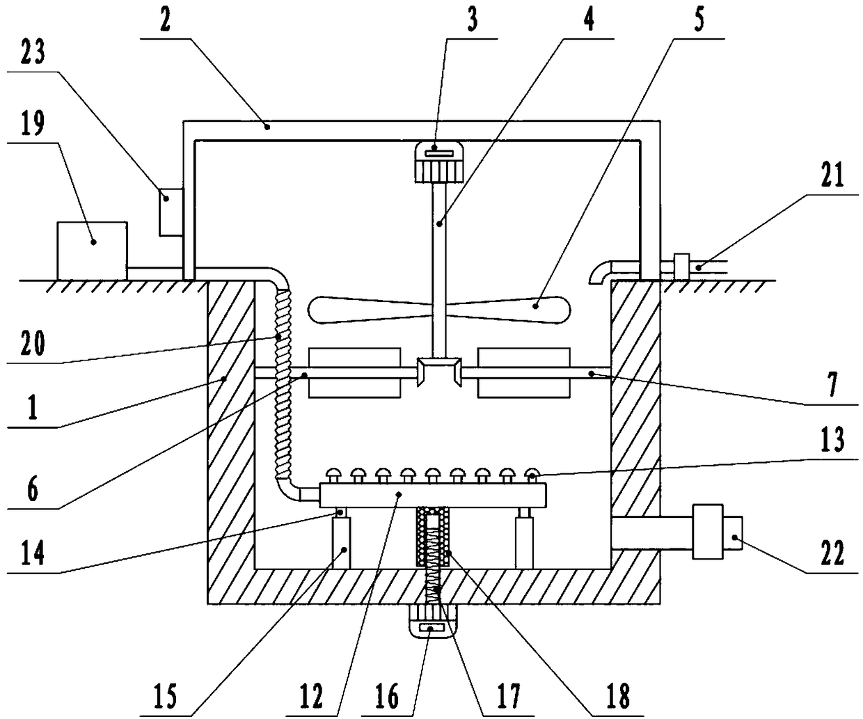
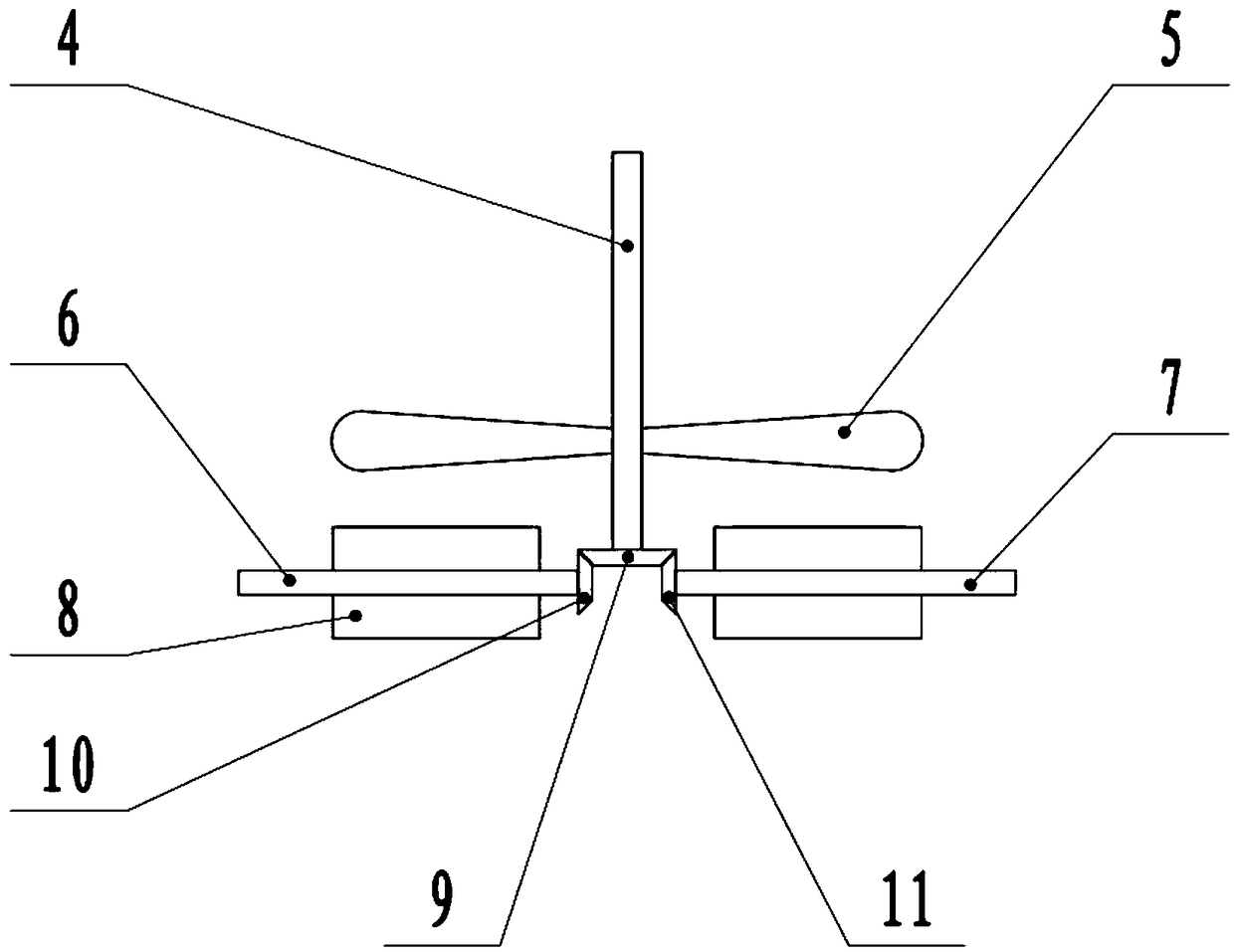
[0022] see Figure 1-3 , in an embodiment of the present invention, an aeration tank that is convenient for adjusting the aeration height includes a tank body 1, a fixed frame 2, an aeration blade 5, a water inlet pipe 21, and a drain pipe 22. The top of the tank body 1 is fixedly connected with a fixed Frame 2, the lower surface of the fixed frame 2 is fixedly connected with the aeration motor 3, the shaft extension end of the aeration motor 3 is fixedly connected with the transmission shaft 4, the lower end of the transmission shaft 4 extends into the pool body 1, and the transmission shaft 4 is fixedly connected There are aeration blades 5. When the aeration motor 3 is running, it drives the transmission shaft 4 to rotate, thereby driving the aeration blades 5 to rotate. The aeration blades 5 are used to raise the surface sewage, so that the surface sewage can fully contact with the air, and aerate the surface sewage , the bottom of the pool body 1 is provided with an aerat...

Embodiment 2

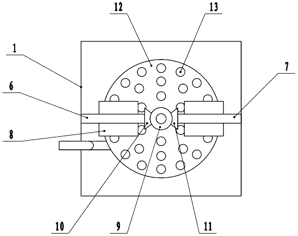
[0025] On the basis of Embodiment 1, the left and right sides of the transmission shaft 4 are respectively provided with a left rotation shaft 6 and a right rotation shaft 7, and the left rotation shaft 6 and the right rotation shaft 7 are respectively connected in rotation with the left side wall and the right side wall of the pool body 1. The rotating shaft 6 and the right rotating shaft 7 are respectively fixedly connected with a stirring plate 8, the lower end of the transmission shaft 4 is provided with a driving bevel gear 9, the right end of the left rotating shaft 6 is provided with a left bevel gear 10, and the left end of the right rotating shaft 7 is provided with a right bevel gear. Bevel gear 11, left bevel gear 10, and right bevel gear 11 mesh with driving bevel gear 9 respectively. When the transmission shaft 4 rotates, it drives the left shaft 6 and right shaft 7 to rotate synchronously, thereby driving the stirring plate 8 to rotate, and using the stirring plate...


PUM


Abstract

The invention discloses an aeration tank capable of adjusting aeration height conveniently, which includes: a tank body, a fixing frame, aeration blades, a water feeding pipe and a water discharge pipe. The fixing frame is fixedly connected to the top of the tank body. An aeration motor is fixedly connected to the lower surface of the fixing frame. A shaft stretch end of the aeration motor is fixedly provided with a transmission shaft. An aeration plate is arranged on the bottom of the tank body. Fixed rods are distributed on the lower surface of the aeration plate. The lower end of each fixedrod is sleeved with a guiding cylinder. A sleeve is fixedly connected to the lower surface of the aeration plate. An adjustment motor is fixedly connected to the lower surface of the tank body. The shaft stretch end of the adjustment motor is fixedly provided with a screw rod. A blower is used for feeding air into the aeration plate for aerating the wastewater at the bottom, wherein the positionof the aeration plate can be adjusted by means of the adjustment motor, so that a user can regulate the aeration height according to practical status. The surface wastewater is raised by the aerationblades and is fully contacted with air for being aerated. The wastewater in the middle layer is stirred by stirring plates, so that the wastewater is fully mixed with bubbles.

Description

technical field [0001] The invention relates to the field of environmental protection equipment, in particular to an aeration tank which is convenient for adjusting the aeration height. Background technique [0002] Domestic sewage is the wastewater discharged from residents' daily life, mainly from residential buildings and public buildings, such as residences, institutions, schools, hospitals, shops, public places and industrial enterprise toilets. The pollutants contained in domestic sewage are mainly organic matter (such as protein, carbohydrates, fat, urea, ammonia nitrogen, etc.) and a large number of pathogenic microorganisms (such as parasite eggs and intestinal infectious viruses, etc.). The organic matter present in domestic sewage is extremely unstable and easily rots to produce stench. Bacteria and pathogens reproduce in large numbers using organic matter in domestic sewage as nutrients, which can lead to the spread of infectious diseases. Therefore, domestic s...

Claims


Application Information

Patent Timeline
IPC IPC(8): C02F7/00
CPCC02F7/00Y02W10/10
Inventor 邹水意邹锦珠
Owner 深圳市金鑫城纸品有限公司
Why Eureka
Try Eureka