
Leather dyeing device

A technology of leather and mounting plate, applied in small raw hide/large raw hide/leather/fur treatment, leather/skin/leather/raw hide chemical treatment equipment, small raw hide/large raw hide/leather hide/fur chemical treatment, etc. Unfavorable printing and dyeing efficiency, time-consuming and laborious, poor leather printing and dyeing quality, etc., to achieve the effect of improving dyeing efficiency, good shock resistance, and simple structure

Active Publication Date: 2018-12-18
温州晨曦工艺品有限公司
View PDF3 Cites 2 Cited by
  • Summary
  • Abstract
  • Description
  • Claims
  • Application Information

AI Technical Summary

Problems solved by technology

[0003] In the processing and manufacturing of leather, it is often necessary to print and dye some special patterns or patterns on the surface of the leather. In the existing leather printing and dyeing processing operations, the leather is generally printed and dyed manually or mechanically. The manual method is time-consuming and laborious. The regularity of printing and dyeing cannot be guaranteed. At the same time, the existing leather printing and dyeing device has a simple structure, and it is inconvenient to adjust the printing and dyeing device when printing and dyeing leather. The printing and dyeing quality is poor
[0004] In order to solve the above problems, the existing patent publication number CN207359848U discloses a printing and dyeing device, but this device only immerses the leather in the dye during printing and dyeing. This printing and dyeing method is too passive and is not conducive to improving the printing and dyeing efficiency.

Method used


Image

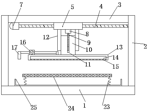
  • Leather dyeing device
  • Leather dyeing device
  • Leather dyeing device

Examples


Embodiment 2

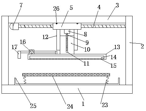
[0025] The difference from Embodiment 1 is that: the upper end of the horizontal slider 5 is symmetrically provided with auxiliary pulleys 26 on both sides, and the lower end of the mounting plate 3 is provided with an auxiliary chute that matches the auxiliary pulley 26. The auxiliary pulley 26 and the auxiliary chute Cooperate to facilitate the sliding of the horizontal slider 5, thus reducing the friction generated by the device.

Embodiment 3

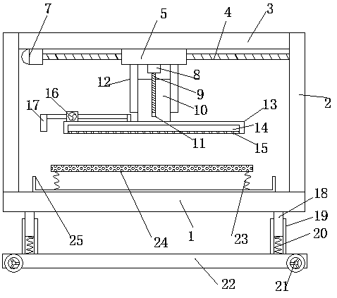
[0027] The difference from Embodiment 1 is that: the lower end of the base 1 is also provided with a buffer mechanism, the buffer mechanism includes a buffer seat 22, and the left and right sides of the buffer seat 22 are symmetrically provided with rollers 21 for convenient device handling, and the rollers 21 are self-locking Roller, the two sides of the upper end of the buffer seat 22 are symmetrically provided with buffer sleeves 19, the upper end of the buffer sleeve 19 slides and is provided with a buffer rod 18, the upper end of the buffer rod 18 is connected and fixed with the base 1, and the inside of the buffer sleeve 19 is provided with a buffer spring 20, the buffer spring 20 connects and fixes the buffer sleeve 19 and the buffer rod 18, and this buffer mechanism greatly improves the shock resistance of the device.


PUM


Abstract

The invention discloses a leather dyeing device. The leather dyeing device comprises a base. A mounting plate is arranged above the base. The left end and the right end of the mounting plate are fixedly connected with the base through supporting plates. A horizontal sliding block is slidably arranged on the lower end face of the mounting plate and is fixedly connected with the mounting plate through a horizontal transmission mechanism. The leather dyeing device is simple and reasonable in structure, convenient to transport and good in shock resistance; to-be-dyed leather is placed on a storageplate, the storage plate is located above a dyeing tank under the effect of reset springs, the horizontal position of a spraying disc is adjusted through the horizontal transmission mechanism, and then the height of the spraying disc is adjusted through a lifting mechanism, so that the storage plate is pressed in the dyeing tank; afterwards, dye in the dyeing tank is pumped into the dyeing disc through a liquid pump, and then the dye is sprayed towards the storage plate through spraying holes, so that active dyeing is achieved, and the leather dyeing effect is improved.

Description

technical field [0001] The invention relates to the technical field of leather processing equipment, in particular to a leather printing and dyeing device. Background technique [0002] Printing and dyeing, also known as dyeing and finishing. It is a processing method, and it is also a general term for pretreatment, dyeing, printing, finishing, washing, etc.; the undergraduate dyeing and finishing major has now been incorporated into the light chemical engineering major; as early as the Neolithic Age six or seven thousand years ago, Our ancestors were able to dye sackcloth red with hematite powder. The primitive tribes living in the Nomuhong area of ​​the Qaidam Basin in Qinghai can dye wool into yellow, red, brown, blue and other colors, and weave woolen cloth with colored stripes. During the Shang and Zhou dynasties, dyeing technology continued to improve. There are full-time official dyers in the palace handicraft workshops to handle grass dyeing and manage dyeing prod...

Claims


Application Information

Patent Timeline
Patent Type & Authority Applications(China)
IPC IPC(8): C14C15/00
CPCC14C15/00
Inventor 缪立超
Owner 温州晨曦工艺品有限公司
Learn More