
Dual-purpose fan control device

A control device and fan technology, which is applied to pump control, pump devices, components of pumping devices for elastic fluids, etc., can solve problems such as repeated start-up of dual-purpose fans and chaotic control functions

Pending Publication Date: 2018-12-18
广州市设计院集团有限公司
View PDF0 Cites 4 Cited by
  • Summary
  • Abstract
  • Description
  • Claims
  • Application Information

AI Technical Summary

Problems solved by technology

However, this multi-party management method is prone to repeated start-up of dual-purpose fans, and the control function is chaotic.

Method used


Image

  • Dual-purpose fan control device
  • Dual-purpose fan control device
  • Dual-purpose fan control device

Examples


Embodiment Construction

[0019] In order to make the purpose, technical solution and advantages of the present application clearer, the present application will be further described in detail below in conjunction with the accompanying drawings and embodiments. It should be understood that the specific embodiments described here are only used to explain the present application, and are not intended to limit the present application.

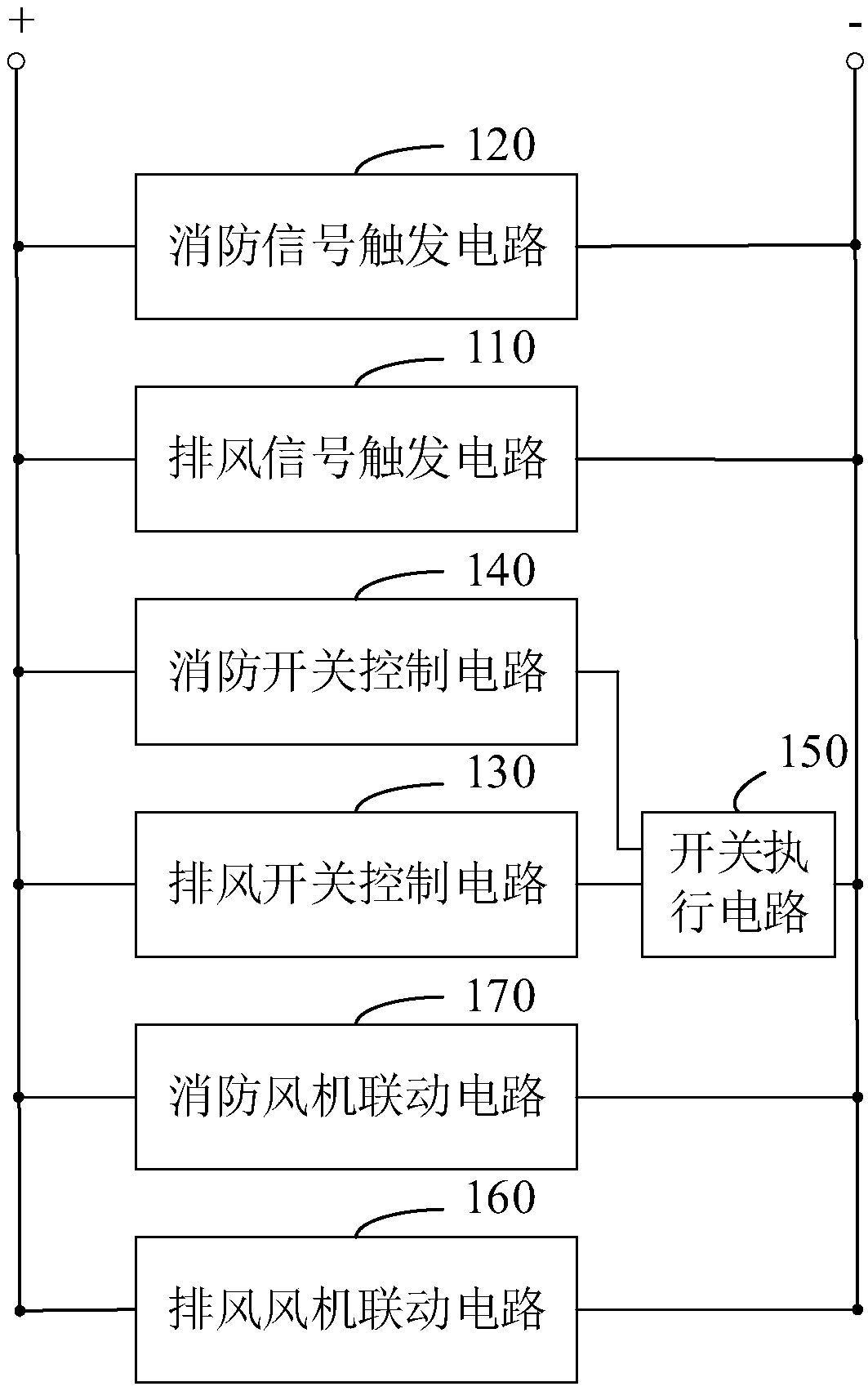
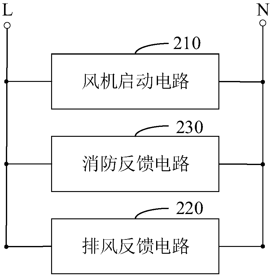
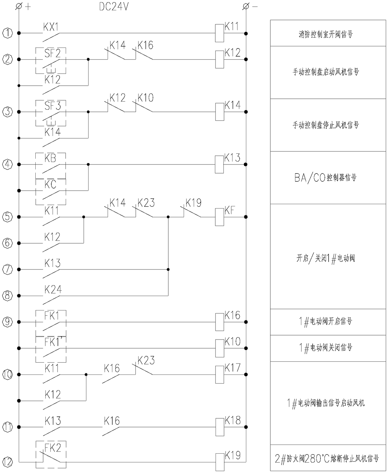
[0020] In one embodiment, a dual-purpose fan control device is provided, which can be applied to control dual-purpose fans that can be used for air exhaust and smoke exhaust; refer to figure 1 and figure 2 The dual-purpose fan control device includes: an exhaust signal trigger circuit 110 connected to direct current, a fire signal trigger circuit 120, an exhaust switch control circuit 130, a fire switch control circuit 140, a switch execution circuit 150, and an exhaust fan linkage circuit 160 It is linked with the fire-fighting fan circuit 170 , and includes a fan start...


PUM


Abstract

The invention relates to a dual-purpose fan control device. The dual-purpose fan control device comprises an exhaust signal trigger circuit, a fire-fighting signal trigger circuit, an exhaust on-off control circuit, a fire-fighting on-off control circuit, an on-off execution circuit, an exhaust fan linkage circuit and a fire-fighting fan linkage circuit, wherein direct current is accessed into theexhaust signal trigger circuit, the fire-fighting signal trigger circuit, the exhaust on-off control circuit, the fire-fighting on-off control circuit, the on-off execution circuit, the exhaust fan linkage circuit and the fire-fighting fan linkage circuit. The exhaust on-off control circuit and the fire-fighting on-off control circuit are both connected with the on-off execution circuit. The on-off execution circuit is connected with an execution mechanism of an electric valve. Alternating current is accessed to a fan starting circuit, an exhaust feedback circuit and a fire-fighting feedbackcircuit. The fan starting circuit comprises an on-off line, a coil of a contactor KM and a main contact of the contactor KM, wherein the on-off line is connected with the coil of the contactor KM, andthe main contact of the contactor KM is connected to a power distribution circuit of a dual-purpose fan in series. By adoption of the dual-purpose fan control device, the linkage relation between theelectric valve and the dual-purpose fan is integrated and perfected; and a control circuit used for exhausting at ordinary times and a control circuit used for exhausting during fire fighting are integrated, so that control is effective, and management is clear.

Description

technical field [0001] The present application relates to the field of fire control technology, in particular to a dual-purpose fan control device. Background technique [0002] A fan is a mechanical device used to move air and can be installed in a building. The fans that can be used for exhausting air at ordinary times and exhausting smoke during firefighting are dual-purpose fans. Generally, the dual-purpose fans can be started and stopped by multiple different management parties, such as building management rooms and fire control rooms. [0003] In the traditional technology, in order to realize the start-stop control of the dual-purpose fan by different management parties, the common management method is that each manager controls the dual-purpose fan through an independent control system. For example, the building property management room adopts the property management system, and the fire control room adopts the automatic fire alarm system; when the dual-purpose fan ...

Claims


Application Information

Patent Timeline
IPC IPC(8): F04D25/08F04D27/00F04D29/00G08B17/06
CPCG08B17/06F04D25/08F04D27/001F04D27/008F04D29/002Y02B30/70
Inventor 江冰周名嘉
Owner 广州市设计院集团有限公司
Learn More