New energy boiler with feeding function

A new energy and functional technology, applied in the direction of solid fuel combustion, furnace grate, double-layer furnace grate, etc., can solve the problems of single boiler structure, inability to realize automatic ash discharge, and inability to realize automatic feeding, so as to improve work efficiency, The effect of saving manpower and novel structure

Active Publication Date: 2018-12-18
唐山冀东石油机械有限责任公司 +1
View PDF5 Cites 2 Cited by
  • Summary
  • Abstract
  • Description
  • Claims
  • Application Information

AI Technical Summary

Problems solved by technology

[0003] The purpose of the present invention is to provide a new energy boiler with feeding function, which can effectively solve the problem that the boiler in the prior art has a single structure, cannot realize automatic feeding, and cannot realize automatic ash discharge; the boiler of the present invention has automatic The function of feeding and automatic ash discharge, novel structure and strong practicability

Method used


Image

  • New energy boiler with feeding function
  • New energy boiler with feeding function
  • New energy boiler with feeding function

Examples


specific Embodiment approach 1

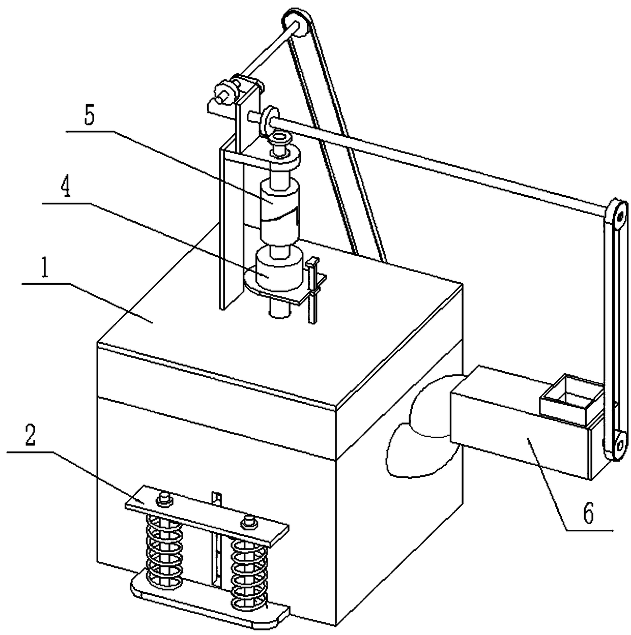
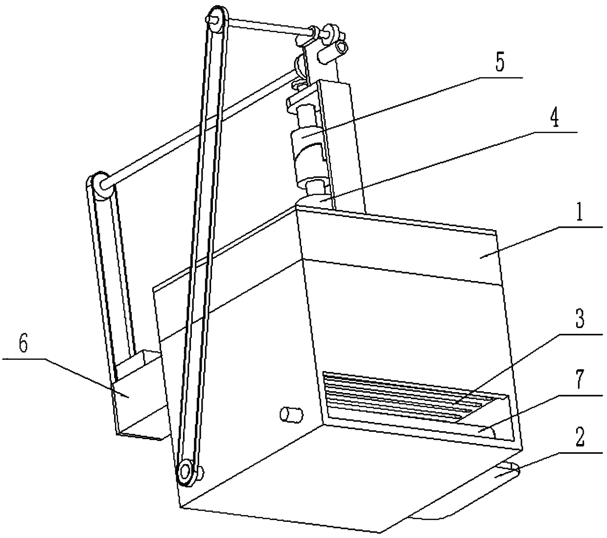
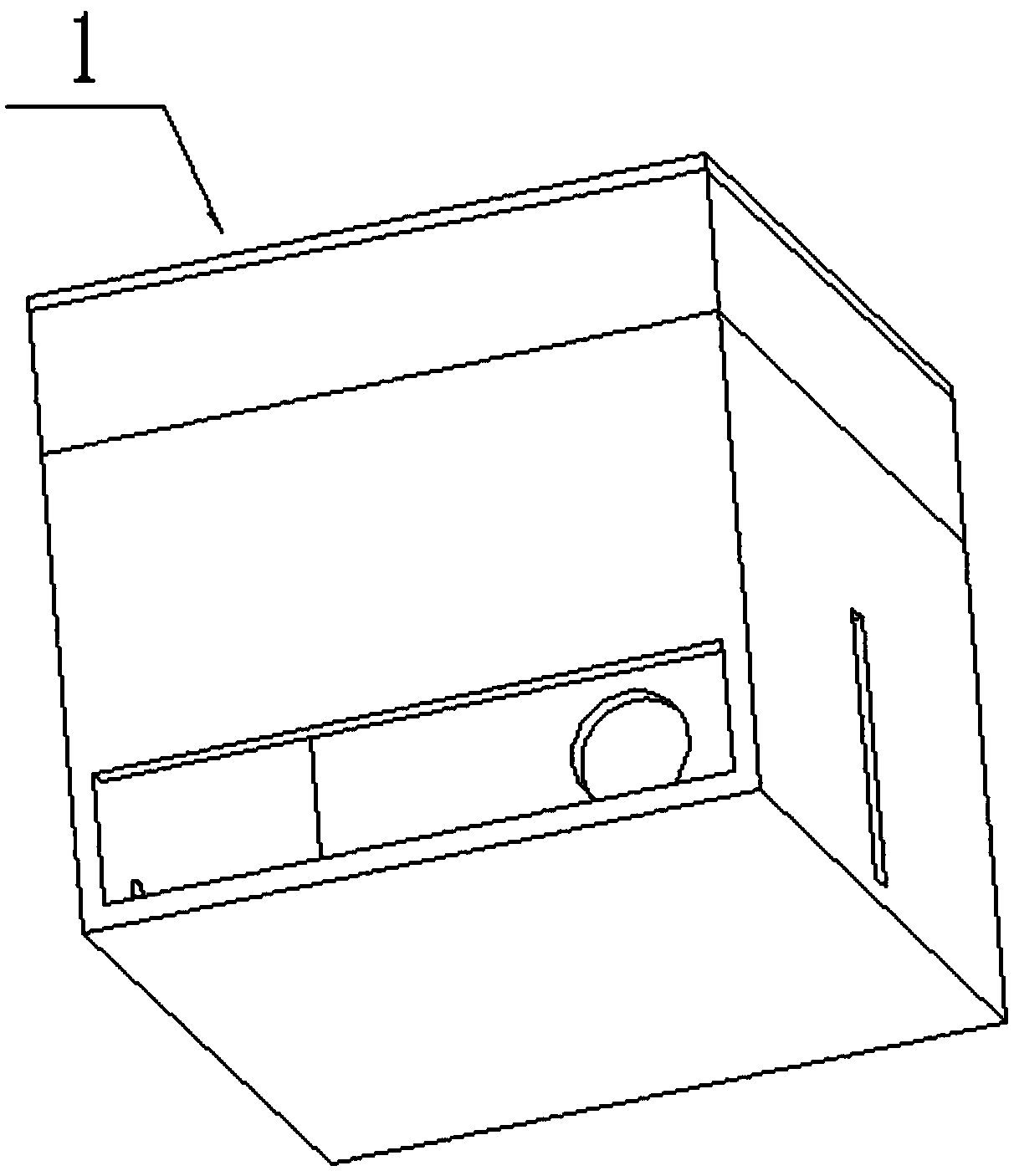
[0024] Such as Figure 1-9 As shown, a new energy boiler with feeding function includes a boiler body 1, a movable grate assembly 2, a fixed grate 3, a motor drive device 4, a transmission device 5, a feeding device 6 and an ash discharge device 7. The fire grate assembly 2, the fixed fire grate 3 and the ash discharge device 7 are sequentially connected to the inner side of the boiler body 1 from top to bottom; On the top surface of the boiler body 1; the upper end of the motor drive device 4 is connected to the transmission device 5; the transmission device 5 is connected to the feeding device 6 and the ash discharge device 7; the charging device 6 is fixedly connected and communicated with the boiler The upper end of the rear side of the body 1; the level of the charging device 6 is higher than the level of the movable grate assembly 2; the lower end of the front side of the boiler body 1 is provided with an ash discharge port, and the ash discharge port is facing the ash d...

specific Embodiment approach 2

[0025] Such as Figure 1-9As shown, the movable grate assembly 2 includes a movable grate body 2-1, a lifting push rod 2-2, a rectangular slider 2-3, a movable plate 2-4, a fixed plate 2-5, and a compression spring 2-6 , spring shaft 2-7 and limit ring 2-8; the middle end of the movable grate body 2-1 is fixedly connected to the lifting push rod 2-2, and the lifting push rod 2-2 is slidably connected to the top of the boiler body 1 On the surface, the top of the lifting push rod 2-2 is fixedly connected to the motor drive device 4; the movable grate body 2-1 is fixedly connected to the movable plate 2-4 through a rectangular slider 2-3; the movable grate body 2- 1. The clearance fit is connected to the inner surface of the boiler body 1, and the rectangular slider 2-3 is slidably connected to the vertical chute on the side of the boiler body 1; the movable plate 2-4 is slidably fitted with two spring shafts 2 -7, the lower ends of the two spring shafts 2-7 are fixedly connect...

specific Embodiment approach 3

[0027] Such as Figure 1-9 As shown, the motor drive device 4 includes a drive motor 4-1, a drive shaft 4-2, a linkage wheel 14-3, a motor seat 4-4 and a rectangular guide rod 4-5; the drive motor 4-1 is fixedly connected On the motor base 4-4, the rectangular guide rod 4-5 is slidably connected to the motor base 4-4, and the lower end of the rectangular guide rod 4-5 is fixedly connected to the boiler body 1; the output of the drive motor 4-1 The end is connected to the drive shaft 4-2 through a coupling; the drive shaft 4-2 is fixedly connected to the linkage wheel I4-3; the linkage wheel I4-3 is connected to the transmission device 5 through transmission. When the motor drive device 4 is working, the drive motor 4-1 drives the drive shaft 4-2 to rotate, and the drive shaft 4-2 drives the interlocking wheel I4-3 to rotate. When the interlocking wheel I4-3 contacts the transmission device 5, it can Drive transmission device 5 to work.


PUM


Abstract

The invention relates to the field of boiler equipment, in particular to a new energy boiler with a feeding function. The new energy boiler with the feeding function comprises a boiler body, a movablegrate assembly, a fixed grate, a motor driving device, a transmission device, a feeding device and an ash discharging device. The movable grate assembly, the fixed grate and the ash discharging device are sequentially connected to the inner side of the boiler body from top to bottom. The upper end of the movable grate assembly is rotatably connected with the motor driving device which is connected with the top surface of the boiler body. The upper end of the motor driving device is in transmission connection with the transmission device. The new energy boiler with the feeding function can effectively solve the problems that a boiler in the prior art has a single structure, cannot realize automatic feeding and cannot realize automatic ash discharging. The new energy boiler with the feedingfunction has the functions of automatic feeding and automatic ash discharging when used, and has novel structure and high practicability.

Description

technical field [0001] The invention relates to the field of boiler equipment, in particular to a new energy boiler with a feeding function. Background technique [0002] Boiler is a kind of energy conversion equipment. The energy input to the boiler is in the form of chemical energy in fuel, electric energy, heat energy of high-temperature flue gas, etc. After conversion by the boiler, it outputs steam, high-temperature water or organic heat carrier with certain heat energy. . The hot water or steam generated in the boiler can directly provide the required heat energy for industrial production and people's life, and can also be converted into mechanical energy through a steam power device, or converted into electrical energy through a generator. But the boiler structure in the prior art is single, can't realize automatic feeding and automatic ash discharge work. Contents of the invention [0003] The purpose of the present invention is to provide a new energy boiler wit...

Claims


Application Information

Patent Timeline
Patent Type & Authority Applications(China)
IPC IPC(8): F23B40/00F23J1/06F23K3/00
CPCF23H5/00F23H11/04F23H11/20F23H11/26F23K3/16F23K2203/202
Inventor 梁春花
Owner 唐山冀东石油机械有限责任公司
Why Eureka
Try Eureka