
Rapid detection method for concrete temperature rise

A detection method and concrete technology, which is applied in the direction of measuring devices, material inspection products, instruments, etc., can solve the problems of inability to respond to the internal temperature rise of concrete, and achieve the effect of fast test data, small workload, and elimination of influence

Active Publication Date: 2018-12-18
武汉三源特种建材有限责任公司
View PDF9 Cites 5 Cited by
  • Summary
  • Abstract
  • Description
  • Claims
  • Application Information

AI Technical Summary

Problems solved by technology

If this research is lacking, it will be difficult to scientifically match the size and material type of the mold used for simulation with the actual situation, so that the results of the simulation test cannot reflect the real internal temperature rise during concrete solidification and curing

Method used


Image

  • Rapid detection method for concrete temperature rise
  • Rapid detection method for concrete temperature rise
  • Rapid detection method for concrete temperature rise

Examples


Embodiment 1

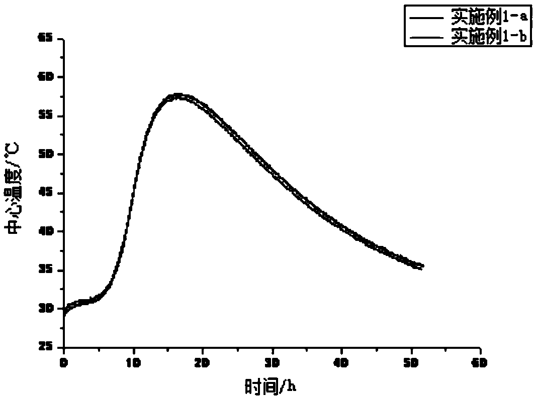
[0051] The concrete used in this example has a strength grade of C50, and the concrete mix ratio is shown in Table 1. The addition method is to mix with cementitious material, admixture, and coarse and fine aggregate first, then add water and water reducing agent, and mix The combined time is not less than 150 seconds, the concrete slump is controlled at 200±20mm, and two data lines are buried at the center of the concrete at the same time. The detection starts after the concrete is completely put into the mold, and the detection frequency is 2 times / min. Since the formwork is usually removed at about 24 hours during the construction of the project site to form heat dissipation conditions, in order to be close to the site, the insulation material on the top of the thermal insulation mold for the test was removed when the concrete was put into the mold for 24 hours. The temperature rise curve drawn is as figure 1 shown.

[0052] Table 1 Example 1 concrete mix ratio

[0053] ...

Embodiment 2

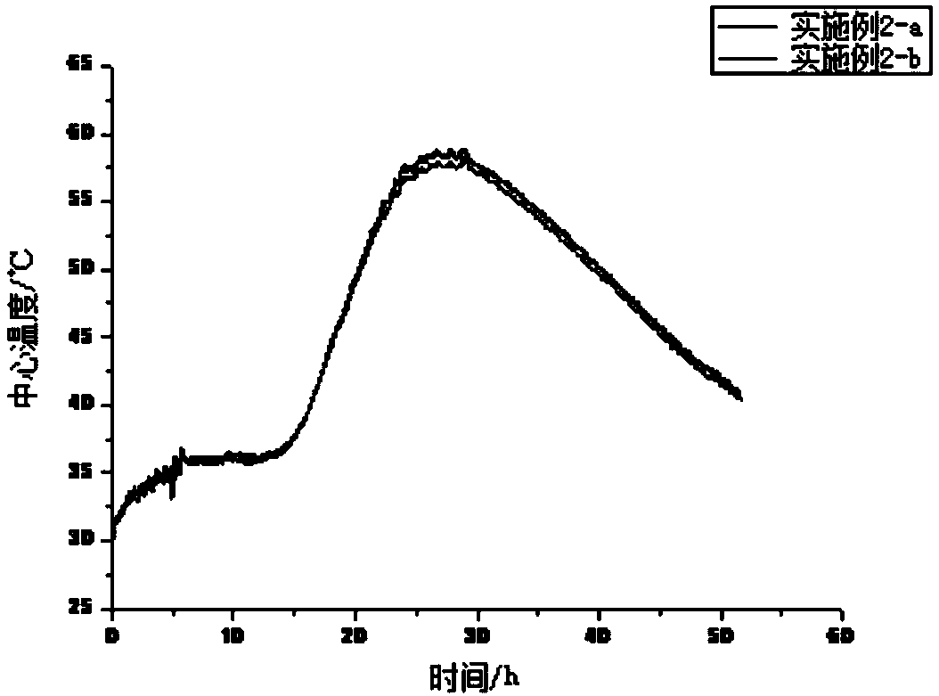
[0055] The concrete used in this embodiment is basically the same as in Example 1, except that a commercially available retarder I (phosphates) is added to the raw materials, and the amount added is 0.07% of the total amount of cementitious materials. The temperature rise curve drawn is as figure 2 shown.

Embodiment 3

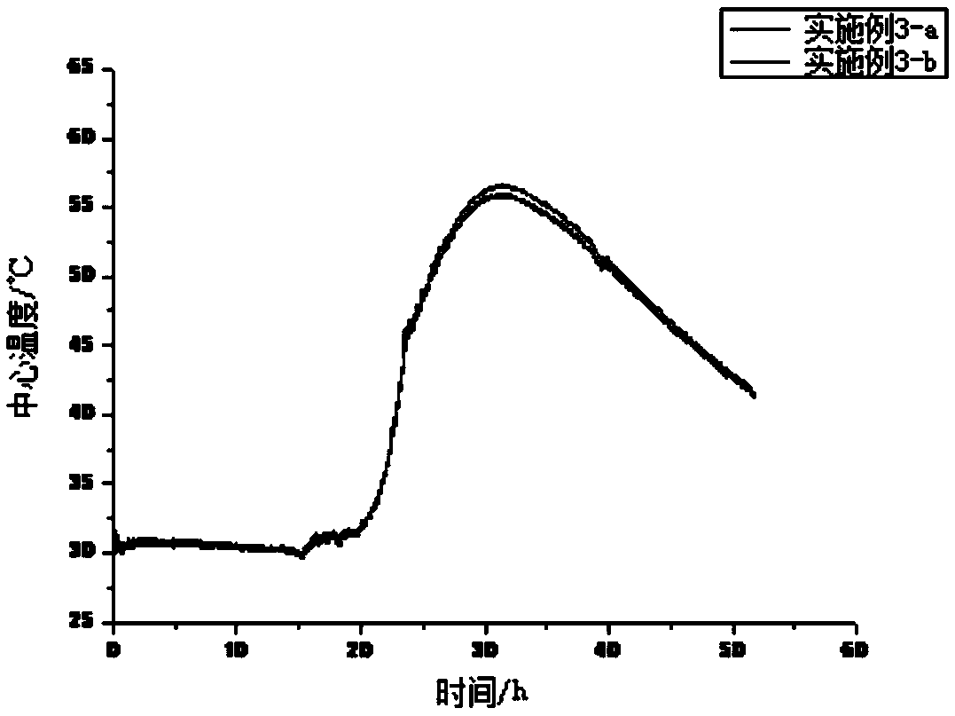
[0057] The concrete used in this embodiment is basically the same as that in Embodiment 1, except that a commercially available retarder I (glucose) is added to the raw materials, and the amount added is 0.07% of the total amount of cementitious materials. The temperature rise curve drawn is as image 3 shown.


PUM

PropertyMeasurementUnit
thermal resistanceaaaaaaaaaa
thicknessaaaaaaaaaa

Abstract

The invention discloses a rapid detection method for concrete temperature rise, comprising the following steps: firstly, selecting one or multiple thermal insulation materials, calculating thickness of each thermal insulation material layer, and laminating to form a single-layer or multi-layer thermal insulation board; secondly, cutting the thermal insulation board according to a certain size andassembling a square thermal insulation mould, and enabling internal capacity size of the thermal insulation mould to be 400-500mm square; and finally, adopting a raw material formula, a preparation method and mould entering conditions which are the same with to-be-detected concrete, and pouring concrete into the thermal insulation mould; then burying a temperature sensor in the concrete, closing an upper cover of the thermal insulation mould, recording temperature inside the concrete according to a set test time interval, and drawing a temperature rise curve. The method disclosed by the invention takes an XPS thermal insulation board with the thickness of 100mm as a standard thermal insulation mould, utilizes a thermal resistance calculation formula for calculating thickness required by athermal insulation board adopting other thermal insulation materials, is not only applicable to a single-layer thermal insulation material but also applicable to a multi-layer thermal insulation material and can more reliably, really, comprehensively and scientifically evaluate variations in the temperature inside the concrete.

Description

technical field [0001] The invention belongs to the technical field of concrete preparation, in particular to a rapid detection method for concrete temperature rise. Background technique [0002] In recent years, with the improvement of the concrete strength grade and the work performance requirements of the mixture, the amount of cementitious materials in concrete has increased, and various admixtures have been introduced, which complicates the cementitious system, causing concrete structures to be unloaded in the early and late stages. The increase of cracks continues to occur, a considerable part of which is due to the rapid accumulation of heat generated by the hydration reaction of the cementitious material, which makes the internal temperature of the concrete rise too fast and too high, and the temperature cracks caused by the excessive temperature difference between the inside and outside of the concrete structure greatly affect It improves the self-waterproof and lon...

Claims


Application Information

Patent Timeline
Patent Type & Authority Applications(China)
IPC IPC(8): G01N33/38
CPCG01N33/383
Inventor 辜振睿刘虎方博侯维红纪宪坤
Owner 武汉三源特种建材有限责任公司
Learn More