Fault branch identification method and system based on T node current

A faulty branch and node current technology, which is applied in the direction of fault location and fault detection according to conductor type, can solve the problem that the faulty branch cannot be accurately identified in T-connected lines

Active Publication Date: 2018-12-18
XUJI GRP +3
View PDF10 Cites 7 Cited by
  • Summary
  • Abstract
  • Description
  • Claims
  • Application Information

AI Technical Summary

Problems solved by technology

[0004] The purpose of the present invention is to provide a faulty branch identification method and system based on the T node current, which is used to solve the problem that the faulty branch cannot be accurately identified when the T-connection line fails

Method used


Image

  • Fault branch identification method and system based on T node current
  • Fault branch identification method and system based on T node current
  • Fault branch identification method and system based on T node current

Examples


Embodiment Construction

[0026] The technical solutions of the present invention will be described in further detail below in conjunction with the accompanying drawings and specific embodiments.

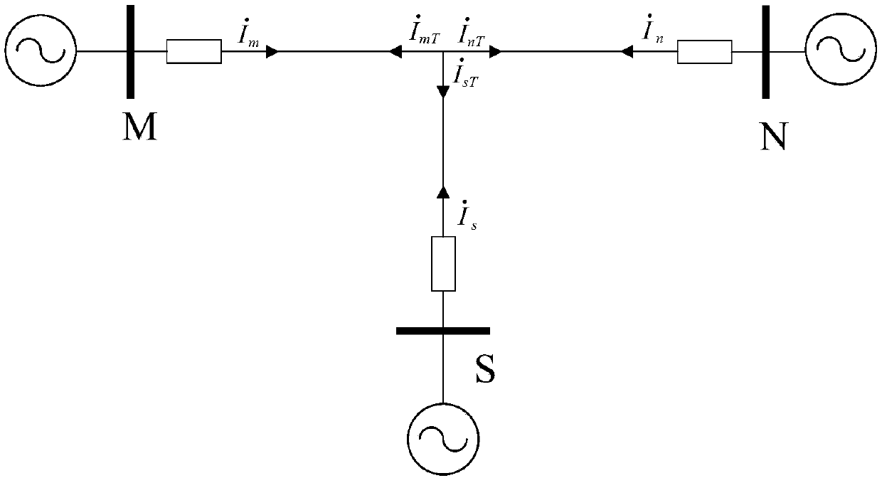
[0027] The wiring diagram of the three-terminal operation of the T-connection line is as follows: figure 1 As shown, including the M side, N side and S side, under normal operating conditions, the currents of the M side, N side and S side lines are respectively and The junction of the three lines on the M side, N side and S side is the T node, and the currents of the T node on the M, N and S sides are respectively and The direction of each current is figure 1 The middle arrow marks the direction.

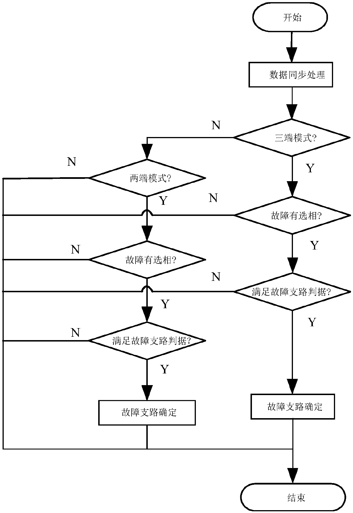
[0028] Based on the wiring mode of the three-terminal operation of the T-connection line, the flow chart of the faulty branch identification method of the present invention is as follows figure 2 As shown, it specifically includes the following steps:

[0029] The first step is to collect the current an...


PUM


Abstract

The invention relates to a fault branch identification method and a system based on T node current, wherein the fault branch identification method comprises steps of: acquiring the current analog quantities as shown in the description on the M side, the current analog quantities as shown in the description on the N side and the current analog quantities as shown in the description on the S side ofthe T-connection line; acquiring the current analog quantities as shown in the description and the current analog quantities as shown in the description of the T nodes on the M, N and S sides; judging whether the T-connection line is a three-terminal mode or a two-terminal mode; performing fault phase selection and judging whether there is a fault phase selection result; and if there is a fault phase selection result, locating fault branch in three-terminal mode or in two-terminal mode according to which is shown in the description, which is shown in the description and Kirchhoff's current law. According to the fault branch identification method and the system based on T node current, when the T-connection line fails, the current on the three sides of the T-connection line and the currenton the three sides of the T-node judged the fault branch according to the Kirchhoff's current law. If the system is normal, the fault branch judging is not performed. The fault branch can be accurately identified, and system misjudgment is avoided.

Description

technical field [0001] The invention relates to a fault branch identification method and system based on T node current, belonging to the technical field of electric power system relay protection. Background technique [0002] With the increase of power load and the increase of domestic grid density, the structure of modern power system is becoming more and more complex, the transmission capacity and voltage level of transmission lines are constantly improving, and the number of long-distance transmission lines is increasing. Starting from the economic benefits of equipment investment and the difficulty of land acquisition, limited by the power supply radius and power supply corridor, considering the limitations of objective conditions and saving investment and other factors, more and more T-shaped transmission lines appear in medium-voltage and high-voltage power grids middle. And these lines are often connected with large power plants and large systems. Due to the high tr...

Claims


Application Information

Patent Timeline
Patent Type & Authority Applications(China)
IPC IPC(8): G01R31/08
CPCG01R31/085
Inventor 赵剑松李宝伟李文正樊占峰姚武李旭姜自强郝慧贞唐艳梅董新涛都磊方正冉志勇严春香唐宇耿继伟
Owner XUJI GRP
Why Eureka
Try Eureka