
Lithography machine matching method

A matching method and technology of lithography machine, applied in the field of lithography machine, can solve problems such as the limitation of optimization degree of freedom, and achieve the effect of high optimization degree of freedom, high matching accuracy and wide adaptability

Active Publication Date: 2020-06-09
SHANGHAI INST OF OPTICS & FINE MECHANICS CHINESE ACAD OF SCI
View PDF4 Cites 2 Cited by
  • Summary
  • Abstract
  • Description
  • Claims
  • Application Information

AI Technical Summary

Problems solved by technology

The prior art adopts Newton's method or the least square method to optimize the light source to realize the matching of the lithography machine (prior technology 2, YuanHe, Alexander Serebryakov and Scott Light et al, A Study on the Automation of Scanner Matching, Proc. SPIE. 7973, 79731H (2013); prior art 3, lithography machine matching method, CN108170006A), but only for parameter adjustment of traditional lighting methods such as conventional lighting, ring lighting, dipole lighting, and quadrupole lighting, or in existing free lighting Intensity or distribution modulation on the mode, its optimization freedom is very limited

Method used

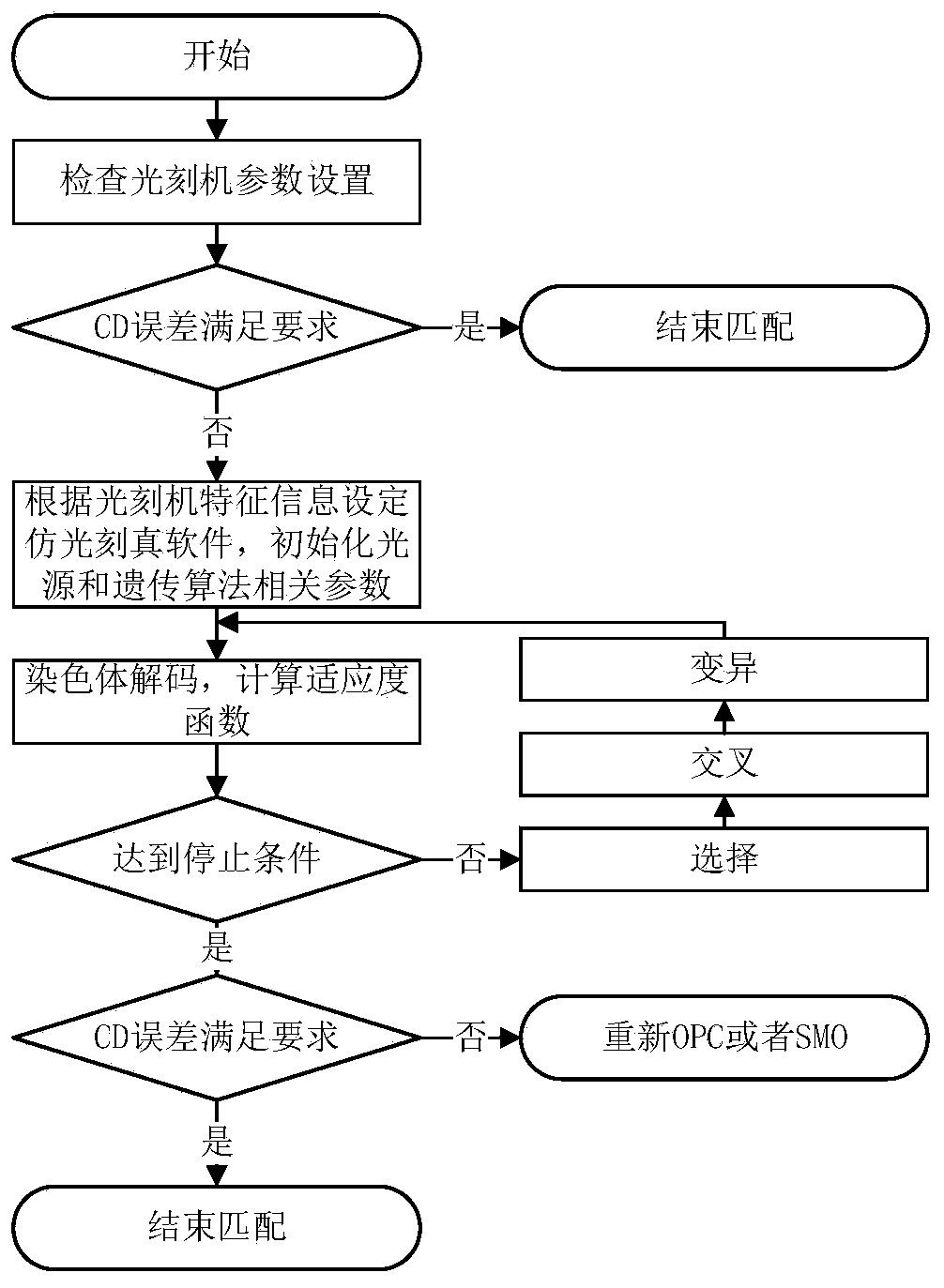

Image

  • Lithography machine matching method
  • Lithography machine matching method
  • Lithography machine matching method

Examples


Embodiment Construction

[0036] The present invention will be further described below in conjunction with the examples and drawings, but the examples should not limit the protection scope of the present invention.

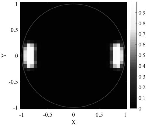
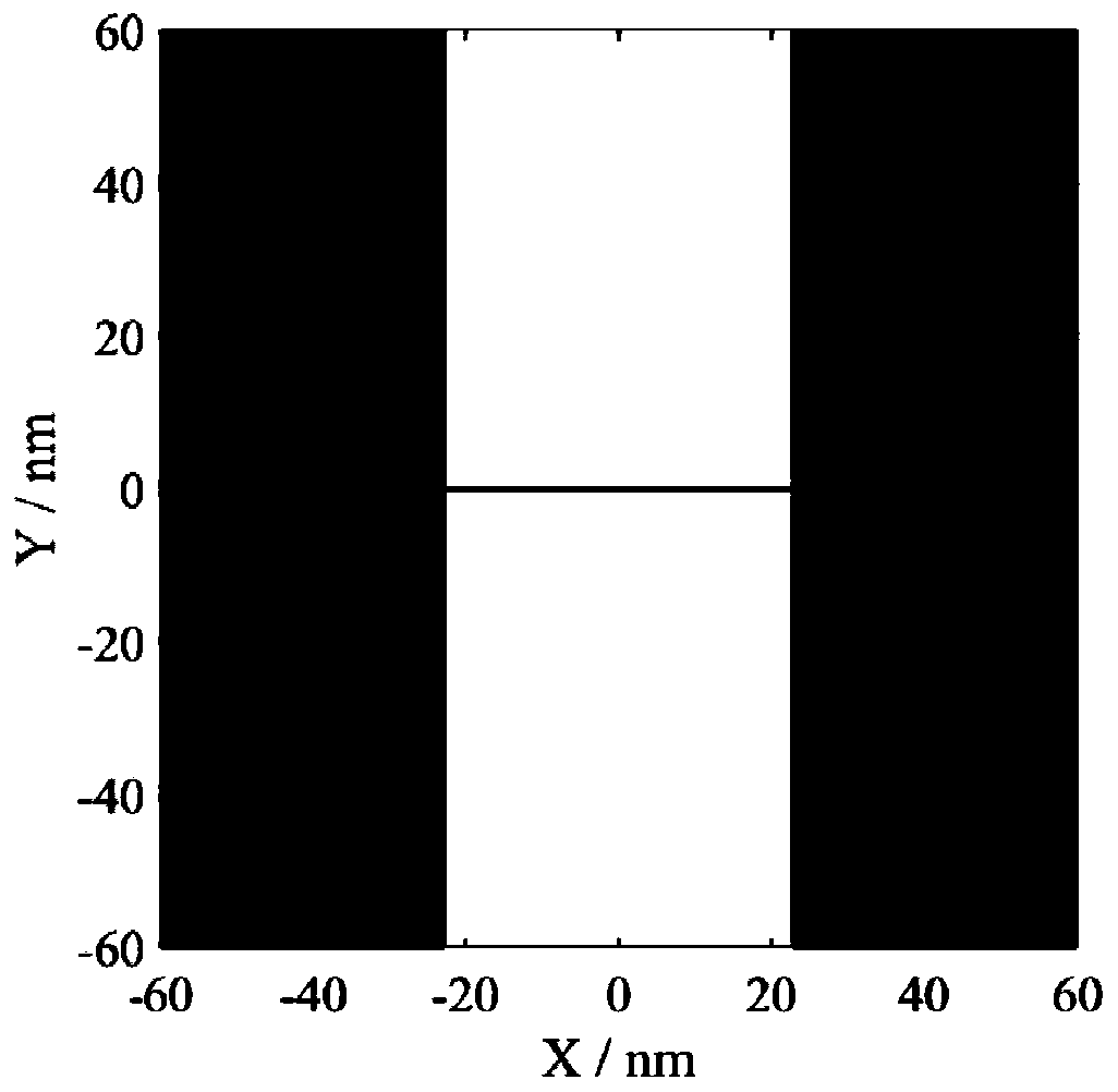
[0037] This embodiment refers to the intensity distribution of the illumination light source of the lithography machine as figure 2 As shown, the luminance value of the white area is 1, the luminance value of the black area is 0, the light source grid is 31×31, and the number of effective light source points within the pupil range is S=709. The test mask and matching mask used are image 3 In the shown one-dimensional through-pitch line-space pattern mask, the line width of the mask pattern is 45nm, the type is a binary mask, the transmittance of the white area is 1, and the transmittance of the black area is 0. The period of the mask pattern is 120nm, 140nm, 160nm, ..., 1000nm, a total of 45, that is, M=45, and the horizontal line segment marked in the figure is the cross-sectional posi...


PUM

PropertyMeasurementUnit
refractive indexaaaaaaaaaa

Abstract

A lithographic machine matching method is provided. The key dimensions of a space image are used as parameters to describe imaging performance of a lithographic machine, illumination light source of lithographic machine described by pixel is optimized by genetic algorithm, and high-precision match between lithographic machines is realized. The invention fully utilizes the advantage of high degreeof freedom of the light source of the free illumination system, improves the matching accuracy of the prior method, and is suitable for matching between the immersion lithography machines or the dry lithography machines with the free illumination system.

Description

technical field [0001] The invention relates to a lithography machine, in particular to a matching method for a lithography machine with a free illumination system. Background technique [0002] Photolithography is the core process of integrated circuit chip manufacturing. In order to reduce economic and time costs, the research and development of lithography processes are usually completed on a specific lithography machine. During mass production of chips, the lithography process needs to be transferred to multiple lithography machines on the production line. There are large differences in the lithography performance of different models of lithography machines. Even the same model of lithography machines may have large differences in lithography performance including imaging quality due to slight differences in their hardware indicators. The performance difference between the lithography machine on the production line, called the lithography machine to be matched, and the...

Claims


Application Information

Patent Timeline
Patent Type & Authority Patents(China)
IPC IPC(8): G03F7/20
CPCG03F7/70458G03F7/7085
Inventor 茅言杰李思坤王向朝
Owner SHANGHAI INST OF OPTICS & FINE MECHANICS CHINESE ACAD OF SCI
Learn More