
A method for optimizing light source of lithography machine

A light source optimization and lithography machine technology, which is applied in the field of lithography machines, can solve problems such as limited degrees of freedom, slow convergence speed, and complex genetic algorithm coding

Active Publication Date: 2016-04-13
BEIJING GUOWANG OPTICAL TECH CO LTD
View PDF5 Cites 0 Cited by
  • Summary
  • Abstract
  • Description
  • Claims
  • Application Information

AI Technical Summary

Problems solved by technology

However, the coding of genetic algorithm is relatively complicated, and its crossover and mutation have typical combination characteristics. The optimization process only operates on the fragments of chromosomes, and the convergence speed is slow.
In addition, the light source pattern in the prior art 3 is represented by simple parameters describing conventional lighting, ring lighting, dipole lighting or quadrupole lighting, and its degree of freedom in optimization is greatly limited

Method used


Image

  • A method for optimizing light source of lithography machine
  • A method for optimizing light source of lithography machine
  • A method for optimizing light source of lithography machine

Examples


Embodiment Construction

[0043] The present invention will be further described below in conjunction with the examples and drawings, but the examples should not limit the protection scope of the present invention.

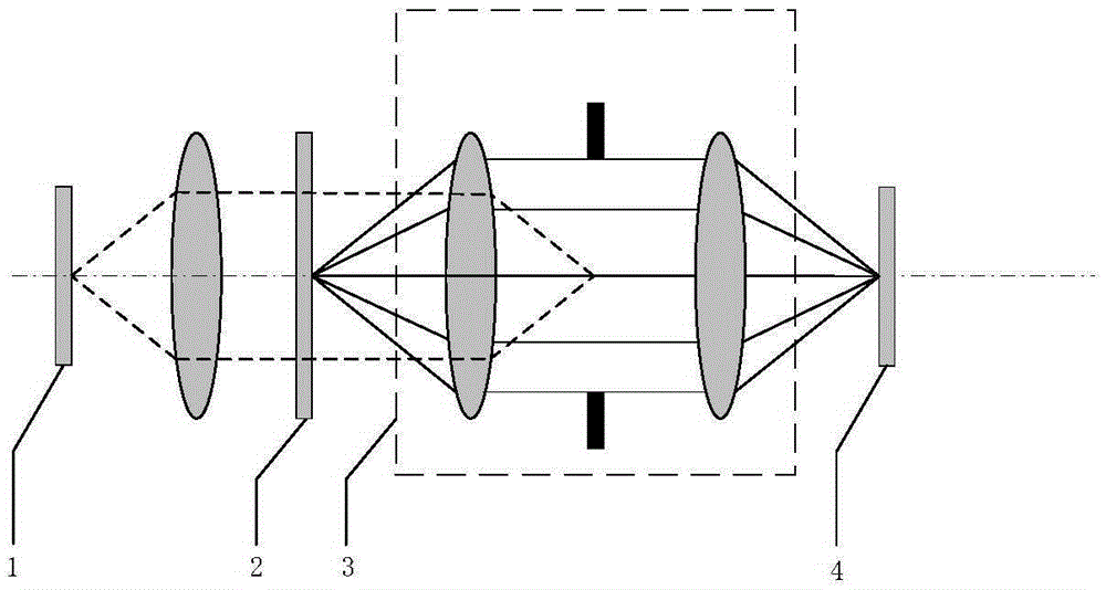
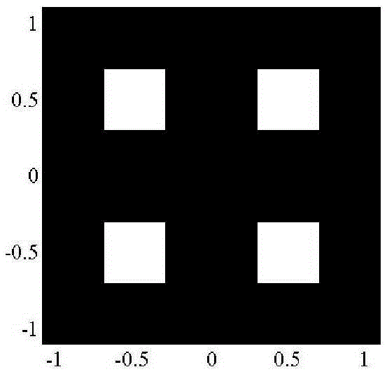
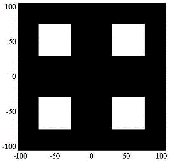
[0044] figure 1 It is a schematic diagram of the lithography machine system used in the present invention. It can be seen from the figure that the method involves a light source 1 for the lighting system of the lithography machine, a mask 2, a projection objective lens 3, and a silicon wafer 4. figure 2 It is a schematic diagram of the initial lighting mode of the light source used in the present invention. The initial lighting mode of the light source is quadrupole lighting, with a size of 11×11 pixels. The brightness value of the white area is 1, and the brightness value of the black area is 0. The partial coherence factor of the lighting mode of the light source σ=0.2. image 3 It is a schematic diagram of the mask pattern used in the present invention. The size of the mask pattern is...


PUM

PropertyMeasurementUnit
refractive indexaaaaaaaaaa

Abstract

A light source optimization method of a photolithography machine. A pixelated light source is employed as particles. Quadratic sum of a difference between each point in an ideal shape and each point in a photoresist image, which is corresponding to a mask, under a present light source illumination mode is used as an objective function. By means of particle swarm optimization containing a linearly decreasing weight and a compressibility factor, light source shape is iteratively optimized by updating speed information and position information of the particles. The method can effectively improve a photolithographic imaging quality, is simple in principle, is easy to carry out and is high in convergence speed.

Description

technical field [0001] The invention relates to a photolithography machine, in particular to a light source optimization method for a photolithography machine. Background technique [0002] Photolithography is one of the most critical technologies in the manufacture of very large-scale integrated circuits, and the resolution of lithography determines the feature size of integrated circuit graphics. In the case of certain exposure wavelength and numerical aperture, it is necessary to reduce the process factor by improving the photoresist process and adopting resolution enhancement technology, so as to improve the photolithography resolution. As an important resolution enhancement technology, Source Optimization (SO) adjusts the intensity and direction of incident light by changing the intensity distribution of the light source. SO can be used alone or as a part of Source Mask Optimization (SMO) to improve lithographic imaging performance. [0003] SO has the advantages of l...

Claims


Application Information

Patent Timeline
Patent Type & Authority Patents(China)
IPC IPC(8): G03F7/20G03F1/76
Inventor 王磊王向朝李思坤闫观勇杨朝兴
Owner BEIJING GUOWANG OPTICAL TECH CO LTD
Learn More