A method for real-time detection of weld seam targets

A real-time detection and target technology, applied in neural learning methods, image data processing, image enhancement, etc., can solve problems such as poor robustness and inaccurate positioning of welding starting points, and achieve simple operation, simple structure, and accurate positioning effect Effect

Active Publication Date: 2018-12-18
SOUTH CHINA UNIV OF TECH
View PDF3 Cites 22 Cited by
  • Summary
  • Abstract
  • Description
  • Claims
  • Application Information

AI Technical Summary

Problems solved by technology

[0004] In view of the above problems, the present invention provides a real-time detection method for weld targets, by collecting and preprocessing training samples, training a weld detector based on convolutional neural network, so that it can quickly and accurately identi

Method used


Image

  • A method for real-time detection of weld seam targets
  • A method for real-time detection of weld seam targets
  • A method for real-time detection of weld seam targets

Examples


Example Embodiment

[0017] The purpose of the present invention will be further described in detail below through specific implementations. The embodiments cannot be repeated here, but the implementation of the present invention is not limited to the following examples.

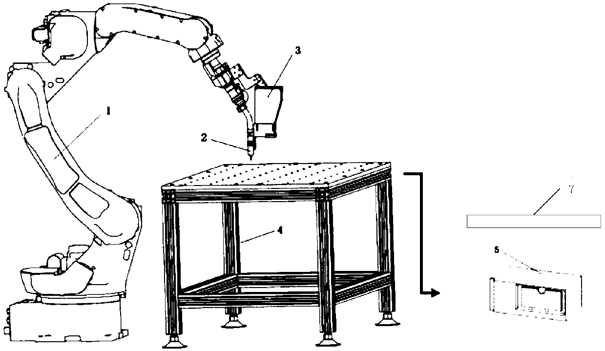
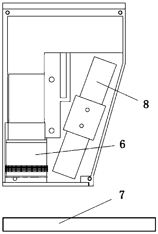
[0018] A method for real-time detection of weld targets. In one embodiment, the method is based on a detection system such as figure 2 As shown, it includes a six-degree-of-freedom manipulator 1, a welding gun 2, a line laser sensor 3, a workbench 4, an embedded controller 5, and a work piece 7. The work piece 7 is placed on the workbench 4, and the line laser vision sensor 3 is installed on the welding gun 2. Above, the welding torch 2 is placed at the end of the six-degree-of-freedom mechanical arm 1, and the line laser sensor 3 and the welding torch 2 change their positions in space by the movement of the six-degree-of-freedom mechanical arm 1. The internal structure of line laser sensor 3 is as image 3 As shown, including came...


PUM


Abstract

The invention belongs to the technical field of detection, in particular to a method for real-time detection of weld seam targets. The method comprises the following steps: building a training sampleset: welding seam images of different shapes are collected as source samples and the source samples are pretreated to form a training sample; training detector offline: the neural network is trained under different initial conditions by using the training samples, and the optimal neural network model is obtained by multiple training as a welding seam detector; performing on-line detection: a detection image is acquired, a weld detection is performed by using the weld detector and a detection result is output. The invention overcomes the problem of poor robustness of positioning the weld seam through the morphological method, realizes the accurate positioning of the weld seam of different shapes, classifies the weld seam of different kinds accurately, and has high positioning precision by adopting the weld seam detector obtained through the weld seam image training based on the line laser imaging for the different weld seams.

Description


Claims


Application Information

Patent Timeline
Owner SOUTH CHINA UNIV OF TECH
Why Eureka
Try Eureka