

A lightweight battery box
A battery box, lightweight technology, applied in secondary batteries, battery pack components, and isolation of batteries from their environment, etc., can solve the problems of large impact of liquid cooling system, reduced liquid cooling efficiency, and easy fire of battery boxes. Achieve the effect of reducing the risk of fire and ensuring the efficiency of liquid cooling
Inactive Publication Date: 2018-12-18
江苏奥特帕斯新能源科技有限公司
View PDF0 Cites 2 Cited by
- Summary
- Abstract
- Description
- Claims
- Application Information
AI Technical Summary
Problems solved by technology
[0002] The tray in the existing power battery box is made of aluminum alloy or steel, without heat preservation and fire prevention measures, which cannot meet the needs of lightweight, and the liquid cooling system is greatly affected by the external environment, which reduces the liquid cooling efficiency. In addition, the battery box is thermally out of control. prone to fire
Method used
View moreImage
Smart ImageViewing Examples

Examples
Embodiment 2
[0021] Same as Example 1, except that the front frame, rear frame, left frame and right frame are made of carbon fiber plates, and the upper frame is formed by bonding four carbon fiber plates.
Embodiment 3
[0023] Same as Example 1, the different front frame, rear frame, left frame, and right frame are composite panels, and the composite panels are formed by sequentially stacking aluminum profiles and bonding carbon fibers from outside to inside.
Login to View More PUM
 Abstract
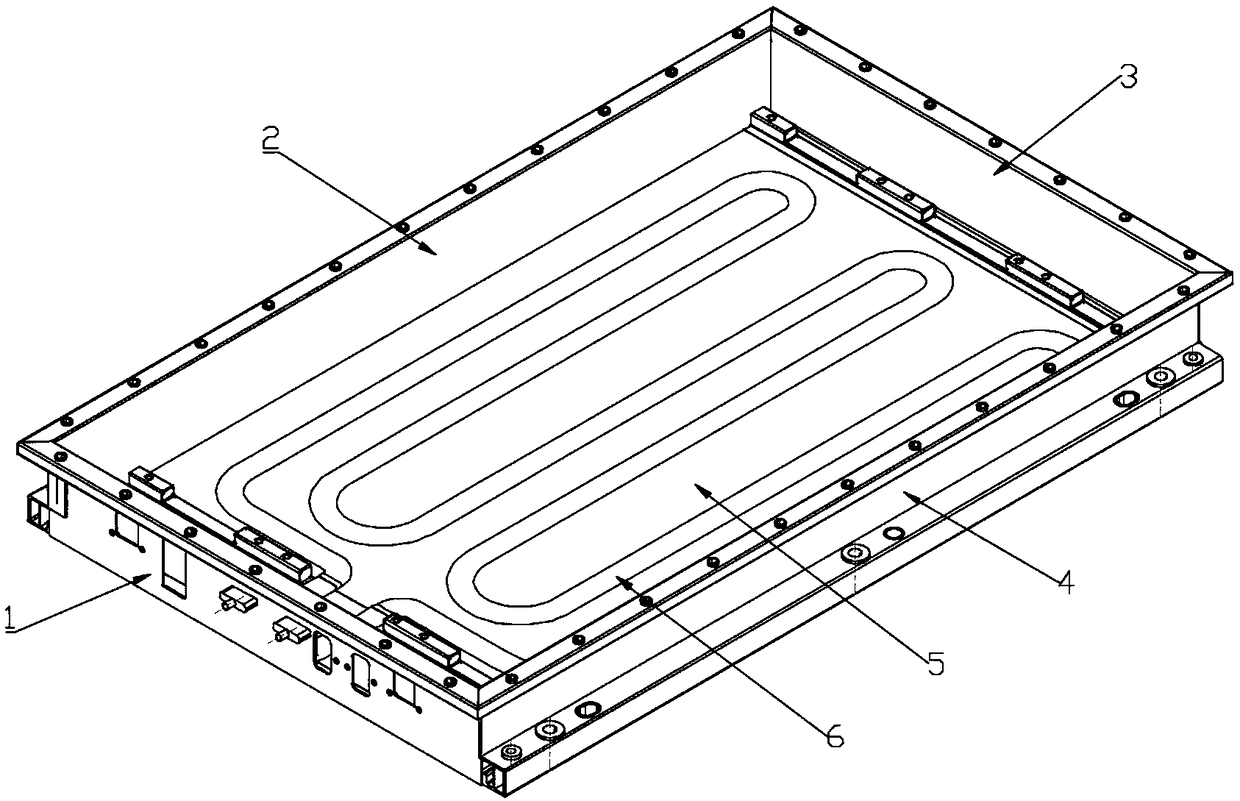
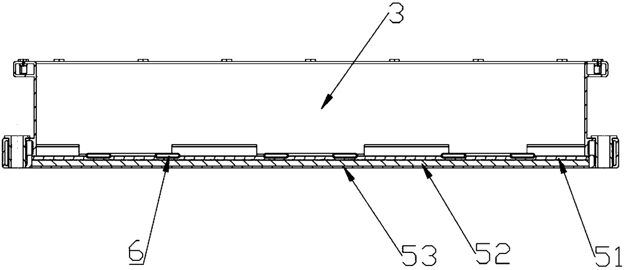
A lightweight battery box includes a tray main body frame formed by splicing a front border, back border, left border, a right border and a bottom plate, a liquid cooling pipe is laid on the upper surface of the bottom plate, the bottom plate comprises an upper bottom plate, a middle bottom plate and a lower bottom plate, the upper bottom plate and the lower bottom plate are made of carbon fiber materials, The middle bottom plate is a high-strength foam plate, the upper bottom plate, the middle bottom plate and the lower bottom plate are infiltrated by resin and solidified and bonded, and a flame retardant is added to the foam plate material, so that the lightweight battery box can ensure the liquid cooling efficiency, reduce the fire risk caused by the thermal runaway of the battery box,and meet the lightweight demand of the tray.
Description
technical field [0001] The invention relates to the technical field of battery trays, in particular to a lightweight battery tray. Background technique [0002] The tray in the existing power battery box is made of aluminum alloy or steel, without heat preservation and fire prevention measures, which cannot meet the needs of lightweight, and the liquid cooling system is greatly affected by the external environment, which reduces the liquid cooling efficiency. In addition, the battery box is thermally out of control. prone to fire. Contents of the invention [0003] The purpose of the present invention is to overcome the shortcomings of the prior art and provide a high-efficiency liquid-cooled battery box. [0004] The present invention is achieved in this way, a lightweight battery box, including a tray body frame spliced by a front frame, a rear frame, a left frame, a right frame and a bottom plate, a liquid cooling tube is laid on the top of the bottom plate, and the ...
Claims
Login to View More Application Information
Patent Timeline
 Patent Type & AuthorityApplications(China)
IPC IPC(8): H01M2/10H01M10/613H01M10/6556H01M10/6568H01M10/658H01M50/20H01M50/24H01M50/247
CPCH01M10/613H01M10/6556H01M10/6568H01M10/658H01M50/20H01M50/24Y02E60/10
Inventor赵志远蒋利波张强
Owner江苏奥特帕斯新能源科技有限公司