Eureka AIR delivers breakthrough ideas for toughest innovation challenges, trusted by R&D personnel around the world.

A superimpose pulse speed regulating drive system and drive method

A technology of superimposing pulses and driving systems, applied in generators/motors, piezoelectric effect/electrostrictive or magnetostrictive motors, electrical components, etc., and can solve the problems of speed oscillation, real-time speed jitter, system instability, etc.

Pending Publication Date: 2018-12-18
NANJING UNIV OF AERONAUTICS & ASTRONAUTICS
View PDF3 Cites 0 Cited by
  • Summary
  • Abstract
  • Description
  • Claims
  • Application Information

AI Technical Summary

Problems solved by technology

like figure 2 As shown, the patent number is US2007 / 0247023 technical scheme, the method of discontinuous pulse output is set in the two phases of sin and cos of the motor, the data of the rotational speed measured through the experiment is as follows image 3 As shown, although this method can obtain the low speed of arc seconds, the real-time speed has a large periodical jitter; the reason is that the motor runs in a continuous periodic start-stop state, and the speed fluctuation of the motor changes from a transient state in continuous operation to a In the normal state of stepping operation, the large inertia system leads to system instability and the consequence of speed oscillation, which has a great impact on the speed stability of the motor

Method used


Image

  • A superimpose pulse speed regulating drive system and drive method
  • A superimpose pulse speed regulating drive system and drive method
  • A superimpose pulse speed regulating drive system and drive method

Examples


Embodiment Construction

[0020] The technical solutions of the present invention will be described in detail below in conjunction with the accompanying drawings.

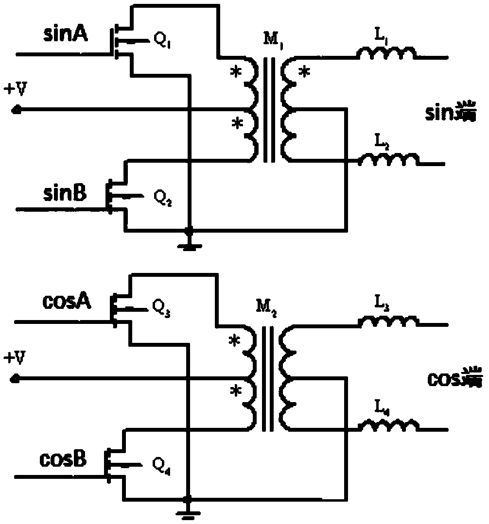
[0021] figure 1 Describe the push-pull circuit of drive system of the present invention, drive system comprises DSP chip and push-pull circuit, DSP chip is provided with four-way PWM output terminals, is connected with sinA, sinB, cosA and cosB of push-pull circuit respectively, sin terminal and cos terminal It is the output terminal of the push-pull circuit, which is respectively connected with the two phases of the ultrasonic motor.

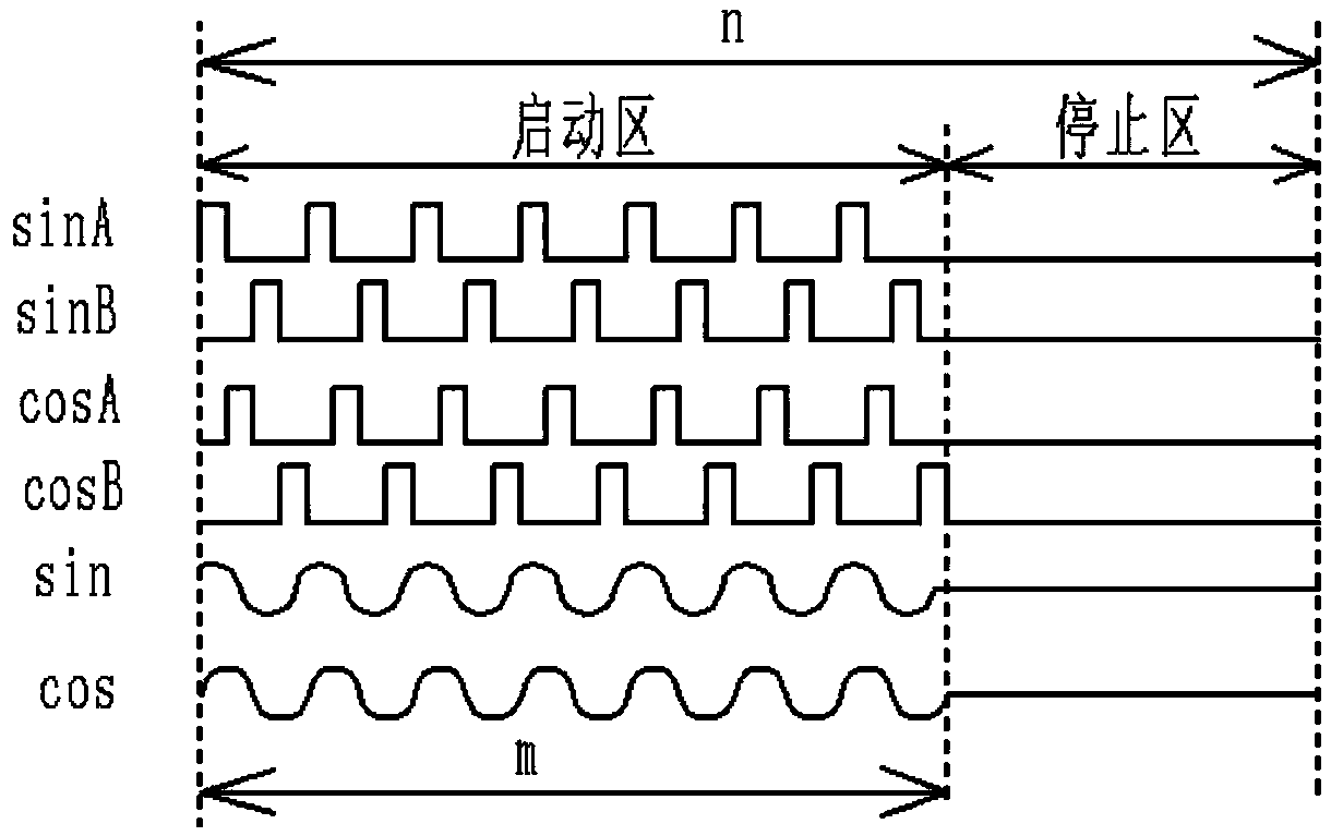
[0022] figure 2 Describe the two-phase discontinuous pulse output method provided in the technical solution of the patent No. US2007 / 0247023. Each cycle of the method is divided into two areas. The sin end and the cos end output pulses are the start area, and the signal sinA and sinB, cosA, and cosB are two pairs of complementary gate drive signals of the push-pull circuit, which are output with a phase o...


PUM


Abstract

The invention provides a superimposed pulse speed regulating driving system and a driving method. In the method, each PWM output terminal outputs a square wave pulse with a duty cycle of 25%. In eachcontrol cycle, sinA and sinB, cosA and cosB output m pulses sequentially in superposition form, and the number of pulses superposed on sin and cos terminals is (2* m-N); Adjust the driving frequency of sin and cos by adjusting the values of m and n to adjust the motor speed and stability. Through the superposed pulse speed regulation driving method provided by the invention, not only the real-timerotational speed does not have large amplitude periodic jitter, The stability of the motor speed is obviously improved, and through the adjustment of some parameters, the motor speed can be adjustedcoarsely and then fine-tuned to achieve the purpose of setting the speed. Compared with the traditional PID algorithm which only changes the frequency, the time taken to adjust the motor speed to theset speed is much shorter, and the response speed of the motor speed is improved.

Description

Technical field: [0001] The invention relates to a superimposed pulse speed regulation driving system and a driving method, belonging to the power supply technology of an ultrasonic motor. Background technique: [0002] Ultrasonic motor, also known as piezoelectric motor, is a new type of driver based on the vibration of ultrasonic frequency of functional ceramics. Ultrasonic motor involves many fields such as vibration, wave science, material science, tribology, electronic science, computing technology and experimental technology. Compared with traditional motors, it has low speed, large torque, fast response speed, and automatic Lock, nanometer resolution, no electromagnetic interference and other characteristics. [0003] Traditionally, motor speed is adjusted through three methods: frequency modulation, voltage regulation and phase modulation, but these three methods have their own disadvantages as low-speed driving methods. The load capacity of the frequency modulatio...

Claims


Application Information

Patent Timeline
Patent Type & Authority Applications(China)
IPC IPC(8): H02N2/14H02N2/16
CPCH02N2/142H02N2/16
Inventor 潘松曾为军徐张凡陈雷唐洪权肖忠
Owner NANJING UNIV OF AERONAUTICS & ASTRONAUTICS
Why Eureka
Eureka Blog
Learn More