Computer signal automatic correction circuit
A technology of automatic correction and signal input circuit, which is applied in the field of circuits, can solve problems such as signal instability and signal distortion, and achieve the effect of improving anti-interference ability
- Summary
- Abstract
- Description
- Claims
- Application Information
AI Technical Summary
Problems solved by technology
Method used
Image

Examples
Embodiment 1
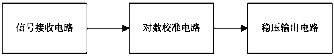
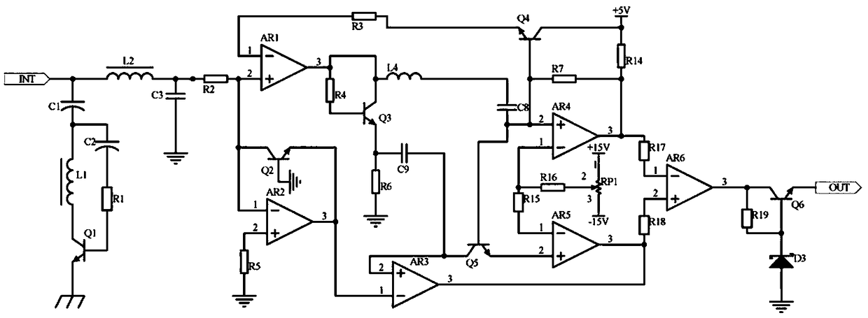
[0013] Embodiment 1, a computer signal automatic correction circuit, including a signal input circuit, a logarithmic calibration circuit and a voltage-stabilizing output circuit, the signal input circuit receives the analog signal at the input end of the signal transmission channel for the computer control terminal to receive signals, and uses the inductor L1 and The composite circuit composed of capacitor C1, capacitor C2 and transistor Q1 completely discharges the abnormal signal to the ground, and the inductor L2 and capacitor C3 are designed to form an LC circuit for filtering. The logarithmic calibration circuit is divided into two ways to receive the signal input circuit and output the signal. One way is input into the non-inverting input terminal of operational amplifier AR1, and the other is input into the logarithmic circuit composed of operational amplifier AR2 and transistor Q2. At the same time, a differential comparison circuit composed of operational amplifier AR4,...
Embodiment 2
[0016] Embodiment 2, on the basis of Embodiment 1, the voltage stabilizing output circuit receives the output signal of the logarithmic calibration circuit, and uses the voltage stabilizing circuit composed of the triode Q6 and the voltage stabilizing tube D3 to output after voltage stabilization, which further improves the stability of the signal Finally, input the computer control terminal to receive the signal in the signal transmission channel, the collector of the triode Q6 is connected to the output terminal of the operational amplifier AR6 and one end of the resistor R19, the base of the triode Q6 is connected to the other end of the resistor R19 and the voltage regulator D3 The negative pole, the positive pole of the regulator tube D3 is grounded, and the emitter of the triode Q6 is connected to the signal output port.
[0017] Implementation 3, on the basis of Embodiment 1, the signal input circuit receives the analog signal at the input end of the signal transmission ...
PUM
 Abstract
Description
Claims
Application Information
 - R&D
- Intellectual Property
- Life Sciences
- Materials
- Tech Scout
- Unparalleled Data Quality
- Higher Quality Content
- 60% Fewer Hallucinations
Browse by: Latest US Patents, China's latest patents, Technical Efficacy Thesaurus, Application Domain, Technology Topic, Popular Technical Reports.
© 2025 PatSnap. All rights reserved.Legal|Privacy policy|Modern Slavery Act Transparency Statement|Sitemap|About US| Contact US: help@patsnap.com