Optical module monitoring system

A monitoring system and optical module technology, applied in the field of optical communication, can solve problems such as high hardware cost, real-time and security limitations, and large overall system size, and achieve the goal of reducing hardware cost, reducing system size, and ensuring work efficiency Effect

Inactive Publication Date: 2018-12-18
WUHAN HENGTAITONG TECH
View PDF2 Cites 14 Cited by
  • Summary
  • Abstract
  • Description
  • Claims
  • Application Information

AI Technical Summary

Problems solved by technology

[0004] In addition, optical fiber communication technology is increasingly used in various harsh environments and high-reliability systems. The transmission rate of optical modules is getting higher and higher, and the number of parallel channels is increasing. Modules need to adopt the scheme of deploying multiple sets of optical module combinations and splicing. This solution not only makes the overall system size large and the hardware cost high, but also the combination of multiple sets of optical modules belongs to asynchronous monitoring, which has limitations in real-time and security.

Method used


Image

  • Optical module monitoring system
  • Optical module monitoring system

Examples


Embodiment Construction

[0023] The principles and features of the present invention will be described below with reference to the accompanying drawings. The examples cited are only used to explain the present invention and not used to limit the scope of the present invention.

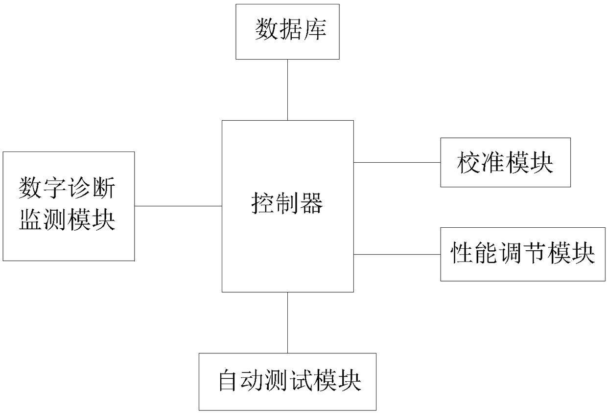
[0024] Such as figure 1 As shown, an optical module monitoring system includes a controller, a digital diagnostic monitoring module, an automatic test module, a performance adjustment module, a calibration module, and a database;

[0025] The digital diagnostic monitoring module is used to monitor the operating parameters during the operation of the optical module according to the operating commands of the controller, and feed back the monitoring results to the controller; the operating parameters are stored in the database;

[0026] The controller controls the performance adjustment module to adjust the modulation current and the bias current of the optical module according to the monitoring result;

[0027] The automatic test module ...


PUM


Abstract

The invention relates to an optical module monitoring system, comprising a controller, a digital diagnosis monitoring module, an automatic test module, a performance adjustment module, a calibration module and a database. The digital diagnostic monitoring module is used for monitoring the running parameters of the optical module according to the operation commands of the controller, and feeding the monitoring results back to the controller; According to the monitoring results, the controller controls the performance adjusting module to adjust the modulation current and bias current of the optical module. The automatic test module is used for automatically calibrating the emitted light power of the emitting end of the optical module and the received light power of the receiving end of the optical module according to the operation command of the controller, and setting calibration parameters of the emitted light power and the received light power; The calibration module is used to read and calibrate the calibration parameters in the database according to the operation commands of the controller. The invention has the beneficial effects that the controller is used to control the digital diagnosis monitoring module and the automatic test module, the optical module is monitored in real time, and the actual value is truly reflected.

Description

Technical field [0001] The present invention relates to the field of optical communication technology, in particular to an optical module monitoring system. Background technique [0002] There are two types of optical modules, which have DDM (digital diagnostic monitoring) functions and those without DDM functions. Those with DDM functions are called smart optical modules. Using smart optical modules, the network management unit can monitor the temperature, power supply voltage, laser bias current, and transmit and receive optical power of the transceiver module in real time. The measurement of these parameters can help the network management unit find out where the fault occurs in the optical fiber link. , Simplify the maintenance work and improve the reliability of the system. [0003] Commonly used DDM solutions are divided into two types: hardware and microcontroller. The hardware solution is simple but lacks flexibility. The microcontroller solution needs to be configured wit...

Claims


Application Information

Patent Timeline
Patent Type & Authority Applications(China)
IPC IPC(8): H04B10/079
CPCH04B10/079H04B10/0795
Inventor 王亚丽杨国民
Owner WUHAN HENGTAITONG TECH
Why Eureka
Try Eureka