Industrial waste gas dust and purification device

A technology for dust purification and industrial waste gas, which is applied in the fields of combined devices, gas treatment, chemical instruments and methods, etc., can solve the problems of difficult promotion, expensive industrial waste gas dust purification equipment, and harm to human living environment and health and safety.

Inactive Publication Date: 2018-12-21
国胜科技(惠州)有限公司
View PDF6 Cites 2 Cited by
  • Summary
  • Abstract
  • Description
  • Claims
  • Application Information

AI Technical Summary

Problems solved by technology

[0002] With the development of the world's industrial economy, the rapid increase of population, the unlimited rise of human desires and the unrestrained production methods, the world's climate is facing more and more serious problems, carbon dioxide emissions are increasing, and the earth's ozone layer is suffering an unprecedented crisis. , the global catastrophic climate change has occurred frequently, which has seriously endangered the living environment, health and safety of human beings. Even the high-speed growth or expansion of GDP that human beings were once proud of has been greatly reduced due to environmental pollution and climate change, and industrial pollution has become more and more serious. It is getting more and more serious, mainly reflected in the fact that industrial waste gas and dust are directly discharged into the air without treatment. For this, many industrial waste gas and dust purification equipment have been derived, but the current industrial waste gas and dust purification equipment is relatively expensive. It is also relatively complicated, and it is not easy to promote. Therefore, an industrial waste gas dust purification device is proposed

Method used


Image

  • Industrial waste gas dust and purification device
  • Industrial waste gas dust and purification device
  • Industrial waste gas dust and purification device

Examples


Embodiment Construction

[0020] The following will clearly and completely describe the technical solutions in the embodiments of the present invention with reference to the accompanying drawings in the embodiments of the present invention. Obviously, the described embodiments are only some, not all, embodiments of the present invention. Based on the embodiments of the present invention, all other embodiments obtained by persons of ordinary skill in the art without making creative efforts belong to the protection scope of the present invention.

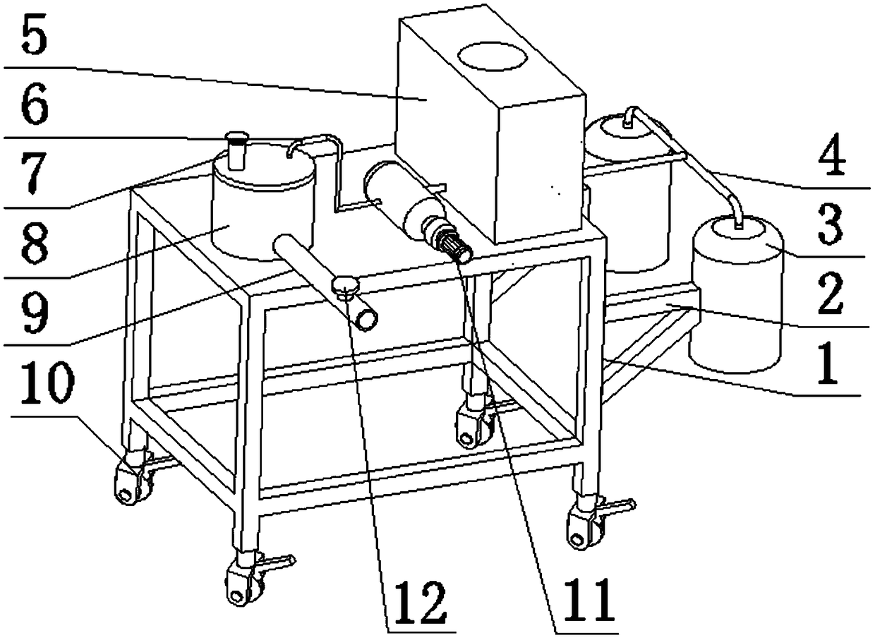
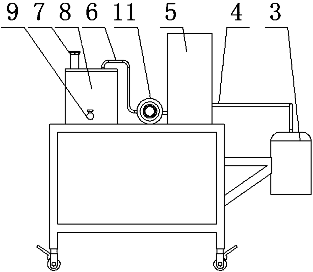
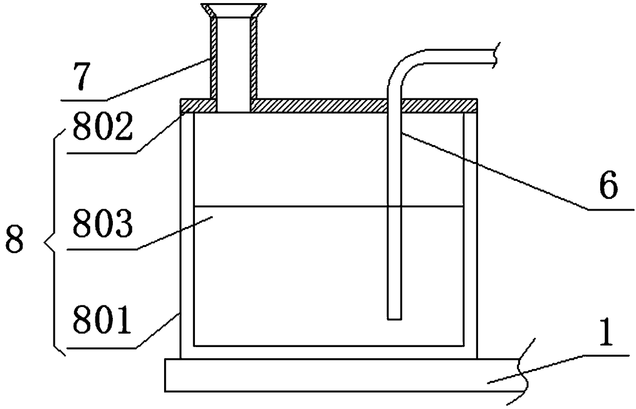
[0021] see Figure 1-6 , the present invention provides a technical solution: an industrial waste gas dust purification device, including a frame 1, two groups of tripods 2 are installed symmetrically on the top of one end of the frame 1, and the tripods 2 are far away from the frame One end of 1 is welded with an air suction device 3 with an opening downward, and the top surface of the frame 1 near the end of the tripod 2 is fixedly equipped with a filter box...


PUM

PropertyMeasurementUnit
pore sizeaaaaaaaaaa

Abstract

The invention discloses an industrial waste gas dust and purification device. Two groups of triangular supports are mutually and symmetrically mounted at the top part of one end of a rack; an air syction device with a downward opening is welded at one end, far away from the rack, of each triangular support; a filtering box is fixedly mounted at one end, close to the triangular supports, on the topsurface of the rack; a top gas outlet of the air suction device is connected with a gas inlet at one end of the filtering box through a T-shaped pipe; dust carries positive charges through electrostatic discharge of a positive charge tungsten wire; all the dust is absorbed through positive and negative attraction of negative charge grid plates and falls into a dust collection channel; dust particles including micro-particles with the size of 0.1 to 0.2mu m, smoke, microorganisms and the like are removed through a glass fiber filtering screen; formaldehyde, organic gas containing lead and thelike are filtered through a photocatalysis special-effect plate, and harmful substances including benzene, undesirable odor and the like are removed through an activated carbon filtering screen; thenfiltered waste gas is discharged into the air through an exhausting pipe; a process is repeated to realize waste gas and dust purification treatment.

Description

technical field [0001] The invention relates to the technical field of industrial waste gas, in particular to an industrial waste gas dust purification device. Background technique [0002] With the development of the world's industrial economy, the rapid increase of population, the unlimited rise of human desires and the unrestrained production methods, the world's climate is facing more and more serious problems, carbon dioxide emissions are increasing, and the earth's ozone layer is suffering an unprecedented crisis. , the global catastrophic climate change has occurred frequently, which has seriously endangered the living environment, health and safety of human beings. Even the high-speed growth or expansion of GDP that human beings were once proud of has been greatly reduced due to environmental pollution and climate change, and industrial pollution has become more and more serious. It is getting more and more serious, mainly reflected in the fact that industrial waste ...

Claims


Application Information

Patent Timeline
Patent Type & Authority Applications(China)
IPC IPC(8): B01D50/00B01D53/00B01D53/60B01D53/75B01D53/79B01D53/86B01D53/72B01D53/64B01D53/04
CPCB01D53/007B01D53/04B01D53/60B01D53/75B01D53/79B01D53/8665B01D53/8668B01D2259/80B01D2251/404B01D2253/102B01D2258/02B01D2257/91B01D2257/70B01D2257/60B01D2257/7027B01D50/60
Inventor 不公告发明人
Owner 国胜科技(惠州)有限公司
Why Eureka
Try Eureka