Stirring device capable of performing automatic discharging

A stirring device and automatic discharge technology, which is applied to mixers with rotating stirring devices, mixer accessories, transportation and packaging, etc., can solve the problems of uneven pressure of stirring paddles, poor homogenization effect, and impossibility of realization, so as to achieve mixing The effect of fast material speed and uniform mixing

Pending Publication Date: 2018-12-21
长兴撒哈拉新材料有限公司
View PDF0 Cites 0 Cited by
  • Summary
  • Abstract
  • Description
  • Claims
  • Application Information

AI Technical Summary

Problems solved by technology

[0002] Stirring is an indispensable process for the preparation of coatings, architectural ceramics, cement, etc. For the stirring of some liquids, a single axial stirring device is generally used. During the stirring process, there will be circular liquid rotation circuits centered on the stirring shaft. , so that some particles with larger mass will stick to the side wall of the liquid tank, while light materials are in the area closer to the rotation axis, resulting in uneven mixing of raw materials or even stratification
The substances in the liquid are not mixed uniformly. It is difficult to achieve homogenization for materials with high viscosity, high density and poor fluidity. During the stirring process, the pressure on the stirring paddle is uneven. There is a circulation loop in the stirring of the paint, and the homogenization effect Poor, paint remains on the inner wall of the cylinder when the paint is output
For the mixing of dry powder or high-concentration slurry, the requirements for the mixing machine will be higher. It is necessary to completely mix the powder to ensure that the materials in all corners of the device can be stirred, which cannot be realized. Stirring with different diameters
The diameter of the stirring rod and the covered area are fixed during the stirring process of the stirring device in the prior art, which is prone to "dead corners" and local powder accumulation
[0003] The existing mixer has poor stirring efficiency and laborious discharge
The traditional mixer needs to be manually scooped or flowed directly from the discharge port at the lower end when discharging. For the slurry with high viscosity and poor fluidity, the slurry will be discharged slowly and wasteful during discharge. At the same time, there will be paint residue on the mixer, resulting in a waste of resources
After the powder mixing is completed, the powder cannot flow out automatically

Method used


Image

  • Stirring device capable of performing automatic discharging
  • Stirring device capable of performing automatic discharging
  • Stirring device capable of performing automatic discharging

Examples


Embodiment Construction

[0019] The present invention will be described in detail below in combination with specific embodiments.

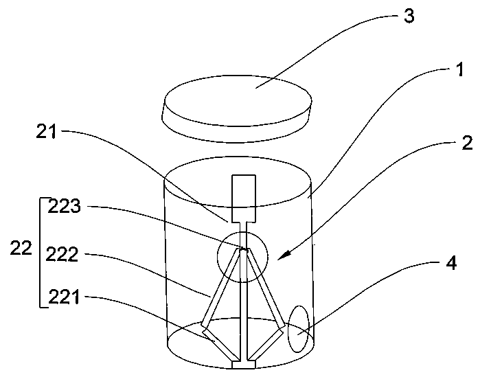
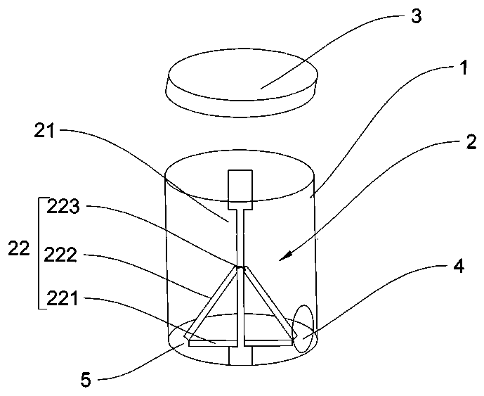
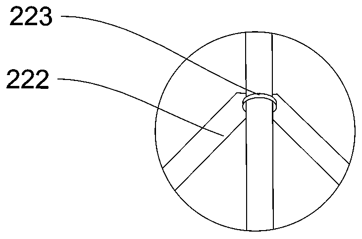
[0020] see figure 1 , figure 2 , image 3 , is a stirring device for automatic discharge, including a cylinder 1, a stirring mechanism 2 is fixed inside the cylinder 1, and the stirring mechanism 2 includes a rotating main shaft 21, a stirring member 22 that is movably connected with the rotating main shaft 21 The stirring member 22 includes a first stirring support 221 movably connected to the bottom end of the rotating main shaft 21, a sliding member 223 sleeved on the rotating main shaft 21 and capable of reciprocating up and down along the rotating main shaft 21, and one end connected to the rotating main shaft 21. The sliding member 223 is movably connected to the second stirring support 222 whose other end is movably connected to the non-fixed end of the first stirring support 221 .

[0021] One end of the first stirring support 221 is flexibly connected with th...


PUM


Abstract

The invention provides a stirring device capable of performing automatic discharging, and relates to the technical field of stirring apparatus. The stirring device comprises a barrel, wherein a stirring mechanism is fixedly arranged in the barrel; the stirring mechanism comprises a rotating main shaft, and a stirring piece movably connected with the rotating main shaft; and the stirring piece comprises a first stirring bracket movably connected with the bottom end of the rotating main shaft, a sliding piece sleeving the rotating main shaft and capable of performing longitudinal reciprocating motion along the rotating main shaft, and a second stirring bracket with one end being movably connected with the sliding piece and the other end being movably connected with a non-fixed end of the first stirring bracket. The stirring diameter of the stirring device can be changed during stirring. The stirring device is uniform in mixing and high in mixing speed. The first sitting bracket can continuously push out mixed materials after mixing, can perform automatic discharging, and cannot leave residual.

Description

technical field [0001] The invention relates to the technical field of stirring devices, in particular to a stirring device for automatic discharge. Background technique [0002] Stirring is an indispensable process for the preparation of coatings, architectural ceramics, cement, etc. For the stirring of some liquids, a single axial stirring device is generally used. During the stirring process, there will be circular liquid rotation circuits centered on the stirring shaft. , so that some particles with larger mass will stick to the side wall of the liquid tank, while light materials are in the area closer to the rotation axis, resulting in uneven mixing of raw materials or even stratification. The substances in the liquid are not mixed uniformly. It is difficult to achieve homogenization for materials with high viscosity, high density and poor fluidity. During the stirring process, the pressure on the stirring paddle is uneven. There is a circulation loop in the stirring of...

Claims


Application Information

Patent Timeline
Patent Type & Authority Applications(China)
IPC IPC(8): B01F7/16B01F15/02B01F15/00
CPCB01F27/0541B01F27/191B01F27/80B01F35/45B01F35/75455
Inventor 钱燕春
Owner 长兴撒哈拉新材料有限公司
Why Eureka
Try Eureka