
Equipment for stabilizing steel tube punch pin

A punch and steel pipe technology, applied in the field of stabilizing steel pipe punch equipment, can solve problems such as instability, and achieve the effect of prolonging service life and avoiding damage

Pending Publication Date: 2018-12-21
江苏宏宝优特管业制造有限公司
View PDF17 Cites 0 Cited by
  • Summary
  • Abstract
  • Description
  • Claims
  • Application Information

AI Technical Summary

Problems solved by technology

[0003] One of the objectives of the present invention is to provide a stable steel pipe punching equipment to solve the technical problem of instability in the process of steel pipe punching in the prior art

Method used


Image

  • Equipment for stabilizing steel tube punch pin
  • Equipment for stabilizing steel tube punch pin
  • Equipment for stabilizing steel tube punch pin

Examples


Embodiment Construction

[0053] In order to make the object, technical solution and advantages of the present invention clearer, the embodiments of the present invention will be further described in detail below in conjunction with the embodiments. It should be understood that the specific embodiments described here are only used to explain the embodiments of the present invention, and are not intended to limit the embodiments of the present invention.

[0054] In the description of the present invention, it should be noted that the terms "center", "upper", "lower", "left", "right", "vertical", "horizontal", "inner", "outer" etc. The indicated orientation or positional relationship is based on the orientation or positional relationship shown in the drawings, and is only for the convenience of describing the present invention and simplifying the description, rather than indicating or implying that the referred device or element must have a specific orientation, or in a specific orientation. constructio...


PUM


Abstract

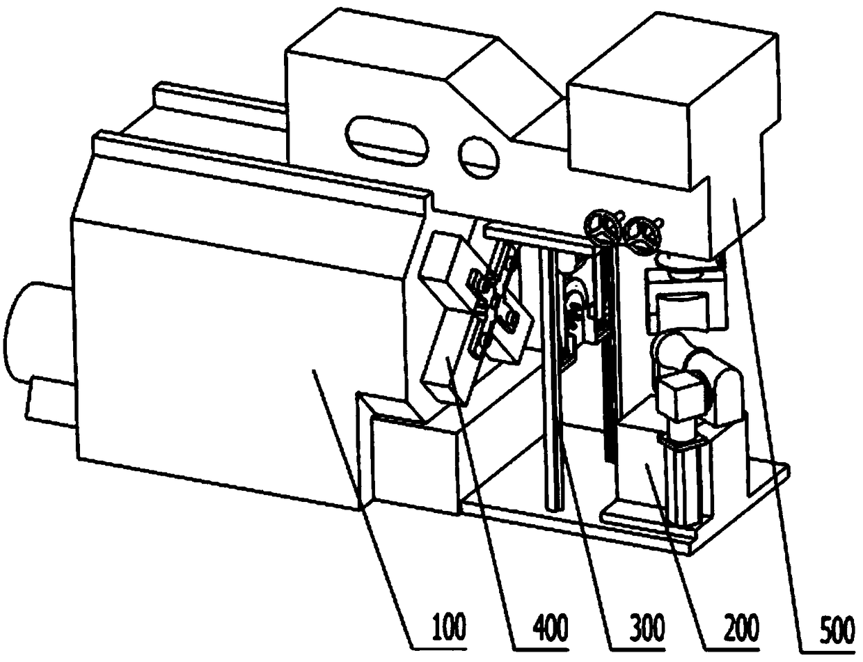
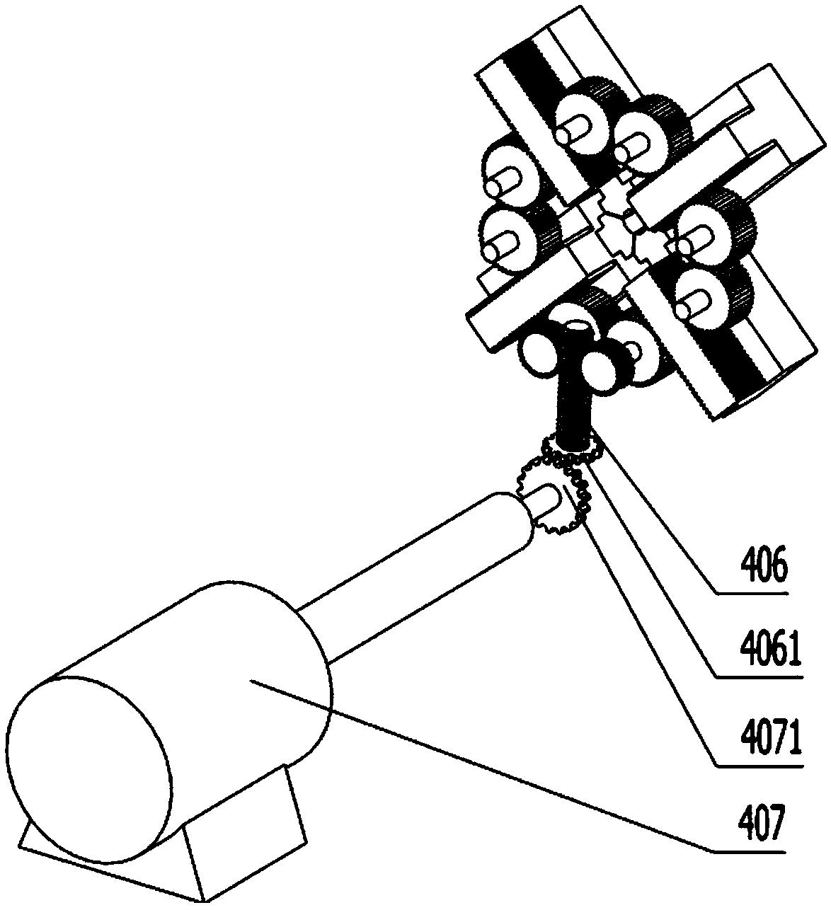
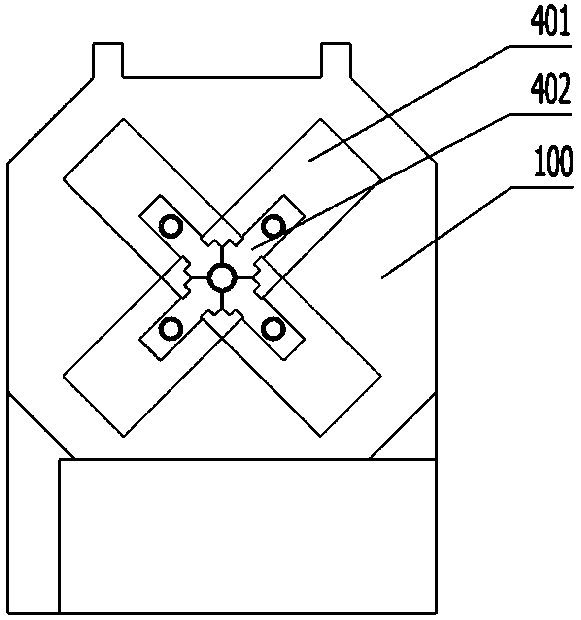
The invention discloses equipment for stabilizing a steel tube punch pin. The equipment for stabilizing the steel tube punch pin comprises a machine body, a punch pin mechanism, a long machine box, asmall machine box and a stabilizing mechanism. The punch pin mechanism is located in the front of the machine body, and a part of the punch pin mechanism is located in the machine body; the long machine box is horizontally arranged in the front of the machine body; the small machine box is located in the front of the long machine box and directly faces the down position, rollers are arranged underthe front ends of the small machine box and the long machine box, and the roller are used for feeding steel tubes into the punch pin mechanism; and the stabilizing mechanism is located between the small machine box and the machine body. The stabilizing mechanism fixes the position of the steel tubes, can counteract the vibration generated in the operation process of the steel tubes, so that the steel tube punch pin is stabilized, and the operation precision of the steel tube punch pin is improved.

Description

technical field [0001] The invention relates to the field of parts processing, in particular to a stabilizing steel pipe punching device. Background technique [0002] Install the steel pipe on the stamping die for continuous stamping and punching operations, so that the processed materials are separated or plastically deformed, so as to obtain the required finished or semi-finished products. This is a common processing method in the field of parts processing. When the steel pipe punching equipment in the prior art is used for punch processing, the position of the steel pipe is easily shifted under the impact force of the equipment, and the punch is unstable. Contents of the invention [0003] One of the objectives of the present invention is to provide a stable steel pipe punching equipment to solve the technical problem of instability in the steel pipe punching process in the prior art. [0004] The second object of the present invention is to provide a punching method ...

Claims


Application Information

Patent Timeline
Patent Type & Authority Applications(China)
IPC IPC(8): B21D41/04B21D43/00B21D55/00
CPCB21D41/04B21D43/003B21D55/00
Inventor 王忠华仲蔡希黄玲王君梅张建红
Owner 江苏宏宝优特管业制造有限公司
Learn More