Improved device for old-fashioned punching machine
What is Al technical title?
Al technical title is built by PatSnap Al team. It summarizes the technical point description of the patent document.
A punching machine, an old-fashioned technology, applied in the field of improvement devices, can solve the problems of low utilization rate of safety materials, low utilization rate of plates, neglected cost, etc., and achieve the effect of saving labor intensity, convenient installation and transformation, and low manufacturing cost.
Inactive Publication Date: 2018-12-21
JIASHAN YONGXIN FASTENER
View PDF7 Cites 4 Cited by
Summary
Abstract
Description
Claims
Application Information
AI Technical Summary
This helps you quickly interpret patents by identifying the three key elements:
Problems solved by technology
Method used
Benefits of technology
Problems solved by technology
In the case of this kind of mass production, the safe production of the punching machine and the utilization rate of the plates are prominent issues: on the one hand, the experience of the workers moving the plates is directly related to the utilization rate of each plate, and in order to speed up the production efficiency, the workers often Will choose to ignore the cost considerations, resulting in low utilization rate of the plate; on the other hand, when the operator is operating, the fast and repeated feeding, stamping, and fittings require the operator to be highly concentrated and have a little negligence. Going to pick up the material will hurt the limbs and cause disability
Therefore, safety issues and low utilization of materials are problems to be solved by old-fashioned punching machines
Method used
Image
Click on the blue label to locate the original text in one second.
Reading with bidirectional positioning of images and text.
Examples
Embodiment Construction
[0018] The present invention will be further described now in conjunction with accompanying drawing.
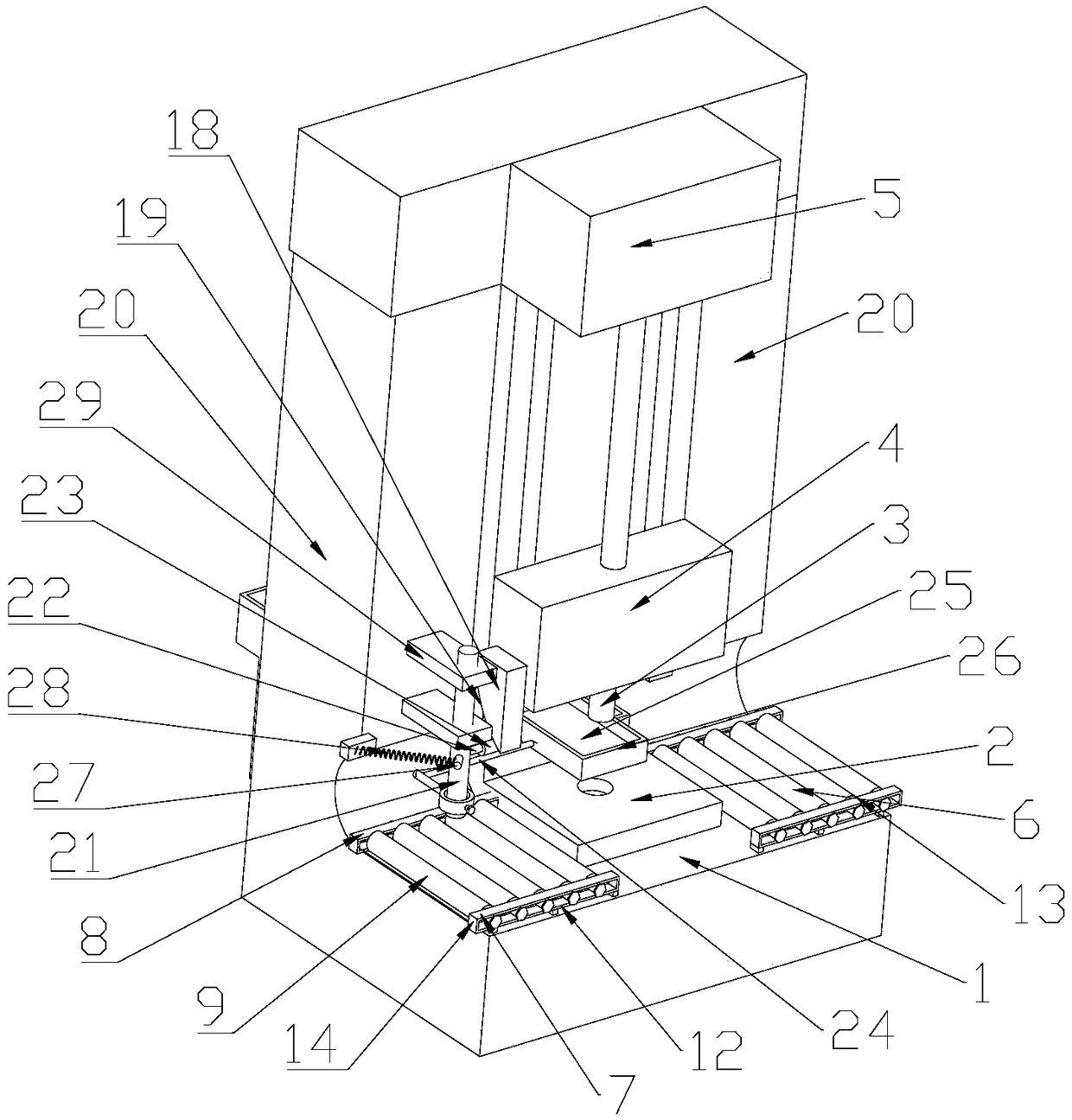
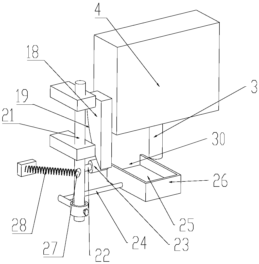
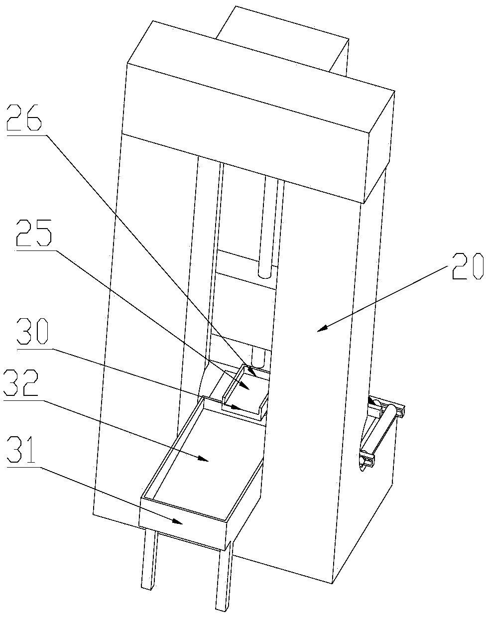
[0019] like Figure 1-4 As shown, an improved device used on an old-fashioned punching machine, the old-fashioned punching machine includes a console 1, a lower mold 2 is arranged on the console 1, an upper mold 3 is arranged above the lower mold 2, and the upper mold 3 is installed on a slide On the block 4, the slide block 4 is driven downward by the driving device 5 for stamping movement, and the operation table 1 on both sides of the lower mold 2 is respectively provided with a conveying device 6, and the conveying device 6 includes a front bracket 7, a rear bracket 8 and Some rollers 9, roller 9 include rotating cylinder 10 and fixed shaft 11, rotating cylinder 10 is installed on the fixed shaft 11 by some bearings, and the two ends of fixed shaft 11 are respectively installed on the front bracket 7 and the rear bracket 8, with The gap distance between the rollers 9 in ...
PUM
Abstract
The invention discloses an improved device for an old-fashioned punching machine. The old-fashioned punching machine comprises an operation platform, a lower die is arranged on the operation table, anupper die is arranged above the lower die, the upper die is mounted on a slider, the slider is driven by a driving device to do downward punching motion, conveying devices are arranged on the portions, on the two sides of the lower die, of the operation platform, each conveying device comprises a front bracket, a rear bracket and a plurality of rollers, and each roller comprises a rotating cylinder and a fixed shaft, wherein the rotating cylinder is mounted on the fixed shaft through a plurality of bearings, the two ends of the fixed shaft are mounted on the front bracket and the rear bracketcorrespondingly, and the gap between the rollers in one conveying device is adjustable. By means of the improved device, the working efficiency of the old-fashioned punching machine is effectively improved, the utilization rate of a plate is improved, meanwhile, the safety of the punching machine can be improved, the advantages of being simple in structure, strong in applicability, reliable in work, high in degree of automation, high in practicability and the like are achieved, double guarantees of the production efficiency and the personal safety are achieved, and the service life of the old-fashioned punching machine is prolonged.
Description
technical field [0001] The invention belongs to the technical field of punching machines, and in particular relates to an improved device used on old-fashioned punching machines. Background technique [0002] With the continuous improvement of the degree of industrialization, various intelligent and automated new punches have been more and more popularized and applied. These new punches not only have high production efficiency, but also ensure safety. However, the price of new punching machines is generally expensive, and enterprises will retain some original old-fashioned punching machines when upgrading equipment. [0003] The old-fashioned punch press moves the material between the upper and lower dies by manually dragging it, and through the continuous impact of the upper die, small punching parts such as gaskets are produced. The working principle of the upper and lower molds is as follows: when the mold is installed on the punching machine and is in working condition,...
Claims
Application Information
Patent Timeline
Application Date:The date an application was filed.
Publication Date:The date a patent or application was officially published.
First Publication Date:The earliest publication date of a patent with the same application number.
Issue Date:Publication date of the patent grant document.
PCT Entry Date:The Entry date of PCT National Phase.
Estimated Expiry Date:The statutory expiry date of a patent right according to the Patent Law, and it is the longest term of protection that the patent right can achieve without the termination of the patent right due to other reasons(Term extension factor has been taken into account ).
Invalid Date:Actual expiry date is based on effective date or publication date of legal transaction data of invalid patent.