Material swinging mechanism

A feeding mechanism and material technology, which is applied to conveyor objects, transportation and packaging, etc., can solve the problems of low welding automation, high labor intensity, unstable product quality, etc., and achieve good welding effect, low labor cost, The effect of a high degree of automation

Pending Publication Date: 2018-12-21
常州新展智能装备有限公司
View PDF0 Cites 3 Cited by
  • Summary
  • Abstract
  • Description
  • Claims
  • Application Information

AI Technical Summary

Problems solved by technology

[0004] 1. The degree of automatic welding is low, and the product quality is unstable;
[0005] 2. The labor intensity is high and the labor cost is high;
[0006] 3. Slow production speed and low efficiency

Method used


Image

  • Material swinging mechanism
  • Material swinging mechanism
  • Material swinging mechanism

Examples


Embodiment 1

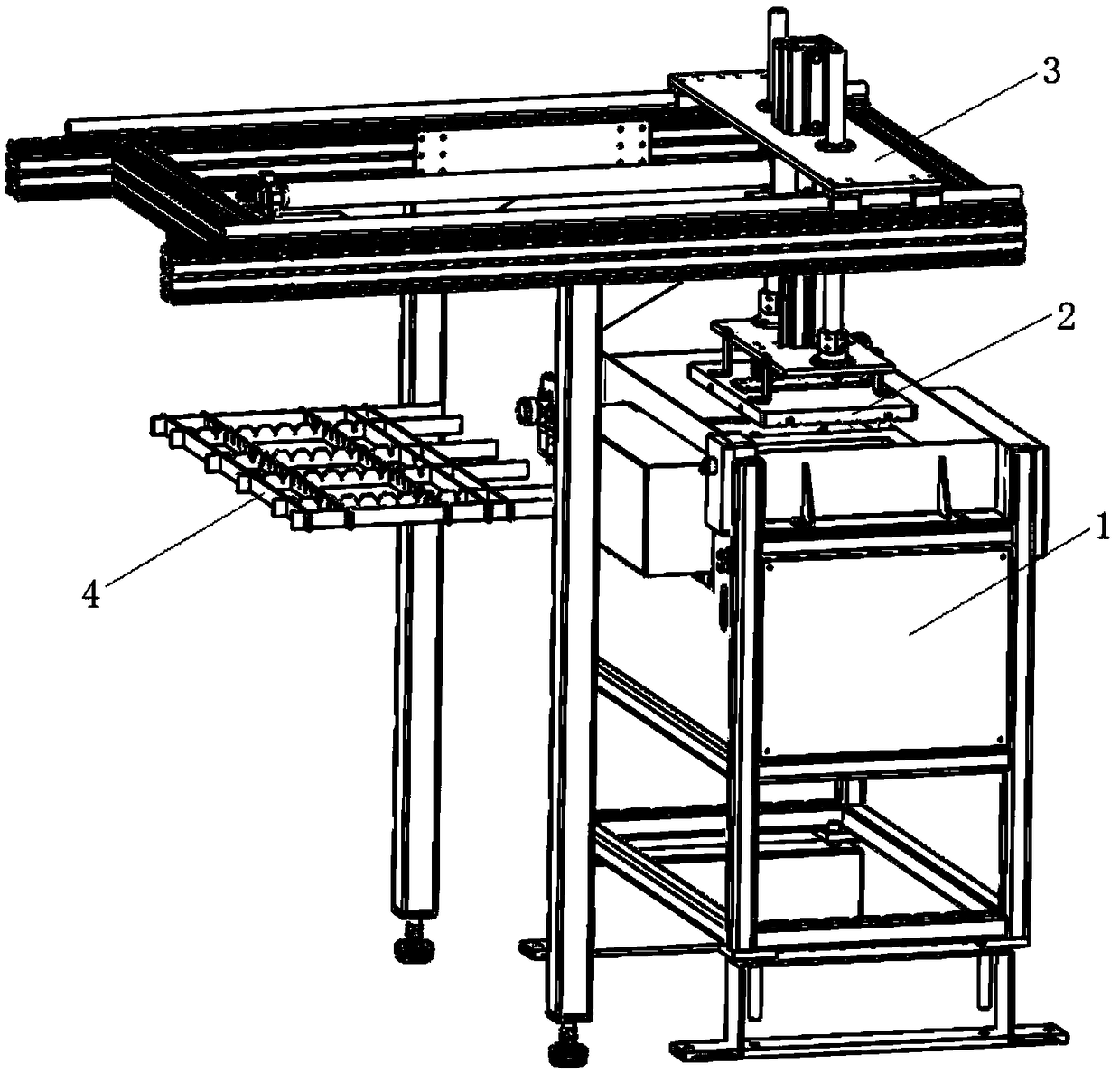
[0040] Such as figure 1 As shown, a material swinging mechanism of the present invention includes a feeding mechanism 1, a feeding mechanism 2 and a tray 4, the feeding mechanism 1 includes a feeding box 11 and a swing assembly for swinging materials, and the feeding mechanism 2 It includes a positioning suction cup 21 arranged above the supply box 11, and a plurality of storage spaces for accommodating materials are arranged on the surface of the positioning suction cup 21 facing the supply box 11. The positioning suction cup 21 is driven by a drive module, and the charging tray 4 There are a plurality of receiving spaces corresponding to the positions of the storage spaces.

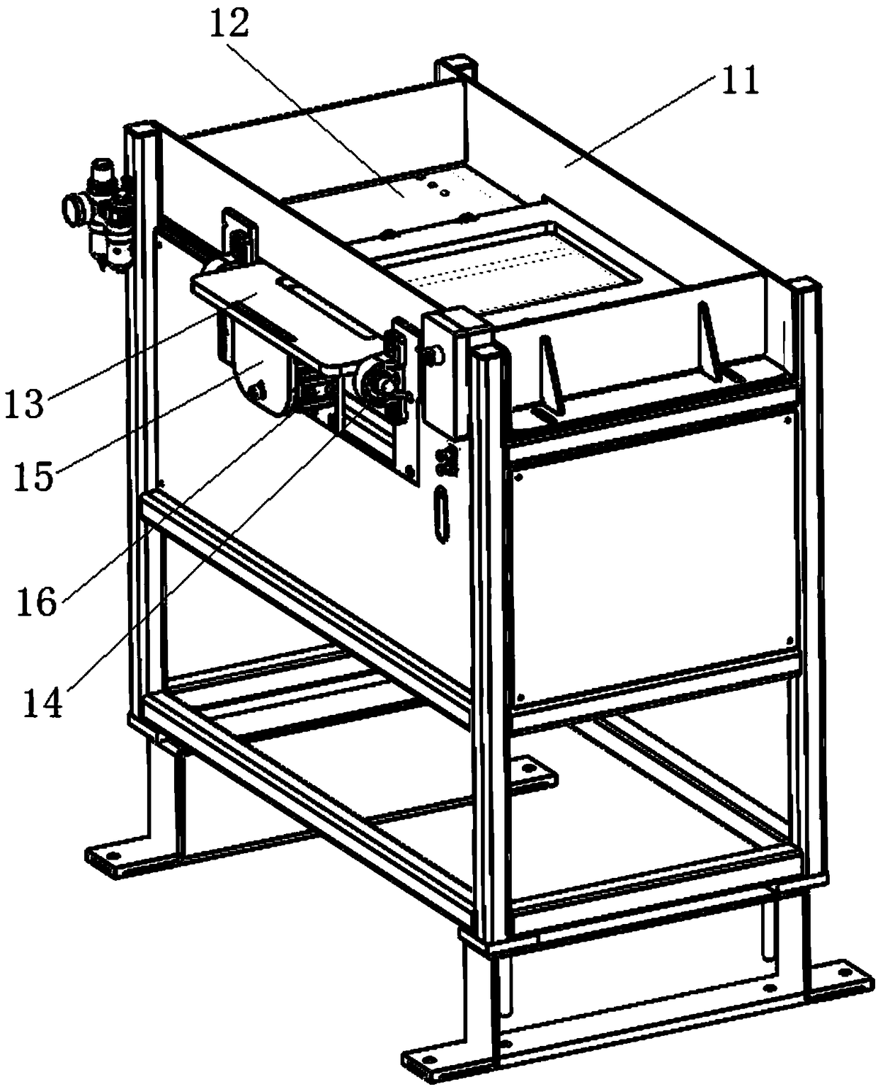
[0041] The swing assembly of this embodiment is as figure 2 As shown, it includes a swing plate 13 arranged at the inner bottom of the feed box 11, the two ends of the swing plate 13 protrude from the feed box 11 and at least one end is connected with a drive cylinder 16, and the drive cylinder 16 dri...

Embodiment approach

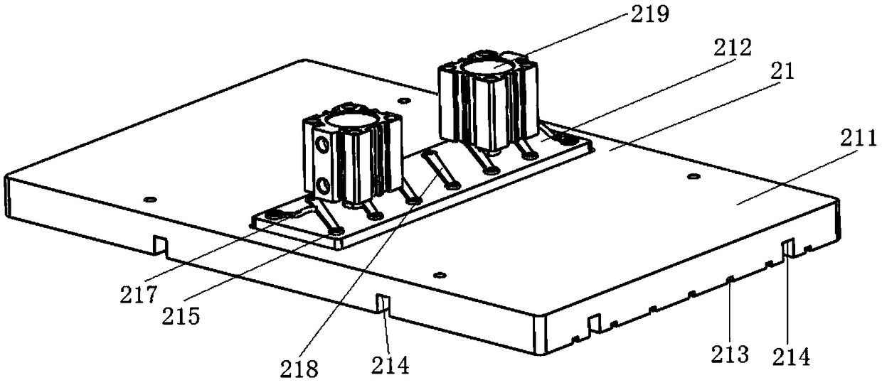
[0048] The first way: if Figure 4 As shown, the pick-and-place mechanism 2 is connected to the feeding mechanism 3, and the feeding mechanism 3 includes a horizontal movement module 31 and a vertical movement module 32 vertically installed on the horizontal movement module 31, and the vertical movement module 32 includes a horizontal movement module 32 arranged in parallel Position the retrieving fixed plate 321 above the sucker 21, and a connector 322 is provided between the retrieving fixed plate 321 and the fixed disc 211 to ensure that the position of the fixed disc 211 is fixed, and one end of the second cylinder 219 is connected with the magnetic module 212, and the other One end is fixed on the material retrieving fixed plate 321, the first cylinder 323 and the third cylinder 325 are arranged on the material retrieving fixed plate 321, and the material retrieving fixed plate 321 moves up and down through the cooperation of the first cylinder 323 and the third cylinder 3...

Embodiment 2

[0054] The structure of this embodiment is basically the same as that of Embodiment 1, the difference is that the swing assembly of this embodiment includes a swing plate arranged at the bottom of the feed box 11, at least one end of the swing plate is connected with a drive cylinder, and the feed box 11 is slidably set , the drive cylinder drives the swing plate to drive the movement of the supply box to swing the material.

[0055] In this embodiment, the magnetic attraction module 212 is an electromagnetic chuck, and the material is a strip-shaped ferromagnetic material, which is absorbed into the storage space of the fixed disk 211 by the electromagnetic chuck. The feeding detection module includes a plurality of sensing elements, and each storage space There is at least one sensing element inside, and the sensing element detects whether the material is successfully obtained in the storage space. If successful, a feedback signal is sent to the PLC to control the feeding mec...


PUM


Abstract

The invention belongs to the technical field of industrial automation, and relates to a material swinging mechanism. The material swinging mechanism comprises a feeding mechanism, a taking and placingmechanism and a material disc. The feeding mechanism comprises a feeding box and a swinging assembly for swinging materials. The taking and placing mechanism comprises a positioning suction cup arranged on the feeding box. A plurality of storage spaces for accommodating the materials are formed in the faces, facing the feeding box, of the positioning suction cup. The positioning suction cup is driven by a driving module. The material disc is provided with a plurality of receiving spaces corresponding to the storage spaces in position. The swinging assembly comprises a swinging plate arrangedat the bottom in the feeding box. The two ends of the swinging plate extend out of the feeding box, and at least one end of the swinging plate is connected with a driving air cylinder. The driving aircylinders drive the swinging plate to swing the materials. According to the material swinging mechanism, the functions of automatically taking and placing the materials are achieved, and the materialswinging mechanism has the advantages of high automation degree, good welding effect, stability, reliability, high precision, high working efficiency and the like.

Description

technical field [0001] The invention belongs to the technical field of industrial automation equipment, and in particular relates to a material swing mechanism. Background technique [0002] Mesh is an indispensable material used in coal mine roof protection, tunnel, bridge construction, roadbed mesh reinforcement, construction sites and other fields. Ordinary mesh is used in the construction industry as Shuleshe board mesh and partition mesh, wall mesh, roadbed steel mesh, and hillside greening guest soil spraying and sowing essential building materials. The external heating galvanized can be used as a flower rack net and a protective net for sea areas in high-salt areas. It can also be made into shelves, heavy goods shelf nets, etc. [0003] In the past, the production of mesh has always been manual operation, with high labor intensity, unstable welding quality, extremely low production efficiency, and relatively few supporting equipment. At this stage, a special weldin...

Claims


Application Information

Patent Timeline
Patent Type & Authority Applications(China)
IPC IPC(8): B65G47/90B65G47/74B65G47/92
CPCB65G47/90B65G47/74B65G47/92
Inventor 刘武生刘官生
Owner 常州新展智能装备有限公司
Why Eureka
Try Eureka