Railway access door management system and railway access door system

A management system and access door technology, which is applied in the field of railway access door management system and railway access door system, can solve the problems of chaotic management of access doors along the railway line and large safety hazards, so as to reduce the pressure of personnel access management and reduce safety hazards , to ensure the effect of safety

Inactive Publication Date: 2018-12-21
中国铁路成都局集团有限公司科学技术研究所
7 Cites 1 Cited by

AI-Extracted Technical Summary

Problems solved by technology

[0003] In view of this, the purpose of the embodiment of the present invention is to provide a railway passage door management system and a ra...

Method used

In sum, the present invention provides a kind of railway passage door management system and railway passage door system, described railway passage door management system is applied to railway passage door system, and described railway passage door management system comprises a plurality of electronic a lock, a base station, and a monitoring platform, the base station is connected in communication with the monitoring platform, the electronic lock is connected in communication with the base station, and the base station is used to transmit the data sent by the electronic lock to the monitoring platform, or Send the control instruction sent by the monitoring platform to the electronic lock, the electronic lock is set on the passage door, and the electronic lock is used to control the opening or closing of the passage door under the control instruction of the monitoring platform , the base station is used to detect the opening and closing state of the electronic lock according to a preset time interval, and send the detected opening and closing state of the electronic lock to the monitoring platform, and the monitoring platform is used to control the electronic lock open or close, and store the opening and closing state of the electronic lock. The railway access door management system and the railway access door system provided by the present invention, by identifying the identity information of the access door, opening and closing the door according to the identity information, and recording the passage information, real-time detection of the opening and closing state of the access door, and the opening and closing status of the access door The closed state is sent to the monitoring platform for storage. Through the monitoring platform, the opening or closing of the access door can be remotely controlled, and the identity information of the personnel entering and exiting the access door can be recorded, which greatly reduces the management pressure of personnel entering and exiting the access door, reduces potential safety hazards, and ensures the safety of railway traffic.
Main control module 131 is as the core control device of base station 130, receives the door lock state information that electronic lock 150 transmits, sends state information and channel door alarm information to system monitoring platform 110 by wireless (or wired) network, receives simultaneously Various commands in the background of the system. Complete the automatic recording of v...

Abstract

The invention relates to the technical field of railway safety, in particular to a railway access door management system and a railway access door system. According to the railway access door management system and the railway access door system, identity information of personnel entering and going out of the access door is identified, the door is opened and closed according to the identity information, traffic information is recorded, the opening and closing states of the access door is detected in real time, the opening and closing states of the access door are transmitted to a monitoring platform to be stored, opening or closing of the access door can be controlled remotely through the monitoring platform, and the identity information of personnel entering and going out of the access door is recorded, so that the personnel entering and existing management pressure of the access door is greatly reduced, the potential safety hazard is reduced and the railway train travelling and operation safety is guaranteed.

Application Domain

Electrical locking circuitsIndividual entry/exit registers +1

Technology Topic

TelecommunicationsManagement system +2

Image

  • Railway access door management system and railway access door system
  • Railway access door management system and railway access door system
  • Railway access door management system and railway access door system

Examples

  • Experimental program(2)

Example

[0031] First embodiment
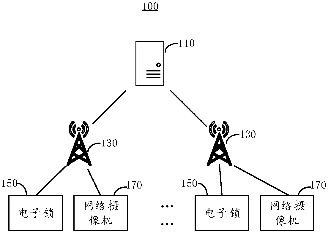
[0032] This embodiment provides a railway access door management system 100 to improve the difficulty of existing railway access door management and there are a lot of potential safety hazards. See figure 1 , figure 1 A schematic diagram of the railway access door management system 100 provided in this embodiment is shown.
[0033] The railway access door management system 100 includes a monitoring platform 110, a plurality of base stations 130, a plurality of electronic locks 150, and a plurality of network cameras 170. Each railway access door is provided with an electronic lock 150 and a network camera 170, a plurality of base stations 130 are communicatively connected with the monitoring platform 110, and each base station 130 is correspondingly communicatively connected with a plurality of electronic locks 150 and a network camera 170. The base station 130 is used to establish communication between the electronic lock 150, the network camera 170 and the monitoring platform 110.
[0034] The base station 130 is used to transmit the data sent by the electronic lock 150 to the monitoring platform 110, or send the control instructions sent by the monitoring platform 110 to the electronic lock 150, and the electronic lock 150 is set in the monitoring platform 110. The access door, the electronic lock 150 is used to control the opening or closing of the access door under the control instruction of the monitoring platform 110, and the base station 130 is used to detect the opening and closing of the electronic lock 150 according to a preset time interval Status, and send the detected opening and closing status of the electronic lock 150 to the monitoring platform 110, the monitoring platform 110 is used to control the opening or closing of the electronic lock 150, and store the opening and closing status of the electronic lock 150 .
[0035] The electronic lock 150 is used to control the opening or closing of the access door. Preferably, the electronic lock 150 can read the user's identity information, and determine whether to open the access door according to the read identity information, or open or close the access door under the remote control of the monitoring platform 110. See figure 2 , The electronic lock 150 includes a main control unit 151, an electromagnetic driver 153, an RFID reading unit 155, a magnetic sensor unit 157, and a communication unit 159. The electromagnetic driver 153, the communication unit 159, the RFID reading unit 155, and the magnetic sensor unit are all electrically connected to the main control unit 151.
[0036] The communication unit 159 is configured to send data to the monitoring platform 110 or receive control instructions sent by the monitoring platform 110 under the control of the main control unit 151. For example, the communication unit 159 may send the identity information read by the RFID reading unit 155, or receive a control instruction sent by the monitoring platform 110, and the control instruction includes opening or closing an access door.
[0037] Preferably, the communication unit 159 selects an RS-485 transceiver. The RS-485 transceiver uses a differential signaling mechanism to realize data transmission in long-distance and noisy industrial environments, suppress common mode noise, and achieve better data transmission effects.
[0038] The electromagnetic driver 153 is used for controlling the opening or closing of the lock bolt under the control of the main control unit 151 according to the control instruction. The electromagnetic driver 153 is a mechanical device controlled by a relay. The relay is electrically connected to the main control unit 151. The relay is used to control the working state of the rotating link, and the rotating link is connected to the lock bolt for controlling the opening or closing of the lock bolt. shut down. When the relay is powered on, the electromagnet is driven to open the rotating connecting rod, and the lock bolt is released to unlock. When the relay is de-energized, the rotating connecting rod will fall, and the lock bolt will lock and close the lock.
[0039] The RFID reading unit 155 is used to identify the electronic label data of the device, and send the identified electronic label data to the main control unit 151. The main control unit 151 controls the electromagnetic driver 153 to turn on or off the electromagnetic driver 153 according to the identified electronic label data. Lock bolt, the main control unit 151 also sends the identified electronic tag data to the monitoring platform 110 through the communication unit 159. For example, the RFID reading unit 155 is used to identify the electronic tag of the device held by the user or staff. The electronic tag of the device can be a "all-in-one card". When the tag approaches, it receives the radio frequency signal sent by the reader and obtains the result by the induced current. The energy sends out the identity information stored in the chip. After the RFID reading unit 155 reads the identity information and decodes the information, it is transmitted to the main control unit 151 for relevant data processing. For example, the main control unit 151 compares the read identity information with the legal identity information sent by the monitoring platform 110, and if there is a match, it controls the electromagnetic driver 153 to open the lock bolt, and at the same time sends the read identity information, door opening time, etc. To the monitoring platform 110. If it does not match, record the abnormal information, and send the abnormal information to the monitoring platform 110.
[0040] The magnetic sensor unit 157 is used to detect the open and close state of the lock bolt, and send the detected open and close state to the main control unit 151, and the main control unit 151 passes the detected open and closed state through the communication unit 159 The base station 130 sends to the monitoring platform 110. Preferably, the magnetic sensor unit 157 can detect state changes such as the locked position of the lock bolt and the closed position of the door through a magnetic induction method, and convert them into electrical signals, which are sent to the main control unit 151. In this embodiment, the opening and closing states detected by the magnetic sensor unit 157 include four types: door unlocked open, door unlocked closed, door closed locked, and door closed locked open.
[0041] In this embodiment, the main control unit 151 may be an integrated circuit chip with signal processing capability. The above-mentioned main control unit 151 may be a general-purpose processor, including a central processing unit (CPU), a network processor (Network Processor, NP), a voice processor, a video processor, etc.; it may also be a digital signal processor. , Application-specific integrated circuits, field programmable gate arrays or other programmable logic devices, discrete gates or transistor logic devices, discrete hardware components. The general-purpose processor may be a microprocessor or the main control unit 151 may also be any conventional processor, such as a PLC (Programmable Logic Controller, programmable logic controller), a single-chip microcomputer, etc.
[0042] It should be noted that in this embodiment, the electronic lock 150 can also be opened with a traditional mechanical key to prevent door lock failure caused by electronic device failure.
[0043] The base station 130 is used to realize the communication connection between the electronic lock 150, the network camera 170, and the monitoring platform 110. The railway access door management system 100 includes a plurality of base stations 130. The base stations 130 may be installed along the railway. For example, a base station 130 may be installed at a preset distance, and the preset distance may be set according to actual network conditions.
[0044] The base station 130 is the core of the entire railway access door management system 100. By receiving the lock and door status data information from the electronic lock 150, the received lock and door status data information is sent to the monitoring platform through the wireless network (or wired) 110, or receive instructions from the monitoring platform 110 via a wireless network (or wired), and control the actions of the electronic lock 150 and the start and stop of the network camera 170 according to the instructions.
[0045] See image 3 , The base station 130 includes a main control module 131, a wireless communication module 133, and a power supply module 135. The wireless communication module 133 is electrically connected to the main control module 131, the wireless communication module 133 is also communicatively connected to the monitoring platform 110, and the power supply module 135 is connected to the main control module 131 and the wireless communication module 133 are electrically connected to supply power to the main control module 131 and the wireless communication module 133.
[0046] The main control module 131, as the core control device of the base station 130, receives the door lock status information transmitted by the electronic lock 150, sends the status information and access door alarm information to the system monitoring platform 110 through the wireless (or wired) network, and receives the background information of the system. Various instructions. Complete the automatic recording of various information of the channel door, complete the automatic detection of internal components, etc.; as an important control unit, the system design adopts low power consumption, high integration, full bus built-in, program and data built-in single-chip microcomputer, and usually Compared with the design of the MCU system with external bus, the program greatly improves the stability of the system. In this embodiment, the main control module 131 may be a single-chip microcomputer, but it is not limited to this.
[0047] The wireless communication module 133 is a communication interface between the base station 130 and the system monitoring platform 110. Responsible for timely transmission of the status information and alarm information of the access door. At the same time, relevant parameter settings of the base station 130 can be performed through the wireless communication module 133.
[0048] The power supply module 135 adopts two power supply modes: AC/DC power supply (AC 220V to DC 12V) and solar panel power supply, and can perform charge monitoring, voltage monitoring and battery power management on the power supply module 135.
[0049] The network camera 170 is in communication connection with the base station 130, and the network camera 170 is used to collect video images entering and exiting the access door according to image collection instructions, and send the collected video images to the monitoring platform 110 through the base station 130. The monitoring platform 110 stores the received video images.
[0050] The network camera 170 is arranged at the access door and is used to collect video images entering and leaving the access door. Generally, when the access door is opened or closed, the base station 130 detects the open or closed status of the access door, and sends the open or closed status of the access door to the monitoring platform 110, and the monitoring platform 110 receives the open or closed status of the access door. Status, that is, an image acquisition instruction is generated and sent to the network camera 170 corresponding to the access door through the base station 130. The network camera 170 collects video images entering and exiting the access door according to the image acquisition instruction, and sends the collected video images through the base station 130 To the monitoring platform 110. The monitoring platform 110 stores the received video images to facilitate subsequent retrieval and viewing.
[0051] In this embodiment, the network camera 170 uses a low-illuminance high-definition camera, which can provide excellent image quality and can support rich functional interfaces such as infrared, alarm, PoE, and photosensitive monitoring. The image sensor of the network camera 170 can adopt CMOS high-quality image sensor, which can output full HD 1080P real-time video; minimum illumination: 0.1LuxF1.2 (color mode), 0.01LuxF1.2 (black and white mode); 3A control: AWB/AF /AE; also has the following communication interfaces: RJ4510M/100M adaptive Ethernet port, compatible with PoE (IEEE802.3af); using network protocols: HTTP, DDNS, DHCP, PPPoE, RTSP, RTP, RTCP, ONVIF; video coding standards For: H.264, MJPEG.
[0052] See Figure 4 The monitoring platform 110 includes a server 111, a display device 113, and an input and output device 115. The display is electrically connected to the server 111 for displaying data and information received by the server 111. The input and output device 115 is electrically connected to the server 111. The connection is used for the input/output device 115 to provide input data for the user to realize the interaction between the user and the server 111. For example, enter the number of the access door that needs to be opened or closed, etc. The input and output device 115 may be, but is not limited to, a mouse, a keyboard, etc., and the keyboard may be a virtual keyboard. In an embodiment of the invention, the input and output unit may also be a voice input device.
[0053] The monitoring platform 110 may send legal identity information to the corresponding electronic lock 150 through the base station 130, the legal identity information includes time information, that is, the identity information can open a specific electronic lock within a corresponding time period 150. When the electronic lock 150 reads the identity information of the user or staff, it compares the read identity information with the legal identity information sent by the monitoring platform 110. When the read identity information is compared with the legal identity sent by the monitoring platform 110 When the information matches, the electromagnetic driver 153 is controlled to open the lock bolt. Thereby opening the access door.
[0054] In this embodiment, the monitoring platform 110 is also used to send control instructions to the electronic lock 150 or send video image collection instructions to the network camera 170. The control instruction may be generated by the server 111 according to the received identity information sent by the electronic lock 150, or may be a control instruction input by a user or a staff member through the input and output device 115. The video image acquisition instruction may be generated by the server 111 according to the received identity information or abnormal information sent by the electronic lock 150. For example, the video image acquisition instruction may be generated when the electronic lock 150 is switched on and off and sent to the station. The network camera 170 may also be a video image capture instruction input by a user or a staff member through the input/output device 115. When detecting that the electronic lock 150 is abnormally opened, the monitoring platform 110 is also used to generate alarm information and send the alarm information to the staff's handheld terminal.
[0055] The working principle of this embodiment: the electronic lock 150 is used to control the opening or closing of the access door, and the network camera 170 is used to obtain the video image of the access door. The electronic lock 150 can read the data in the electronic tag of the device held by the user or staff, control the door lock to open when the read data matches the data sent by the monitoring platform 110, and send the read data to the monitoring platform 110 for storage to facilitate the access management of the access door. The base station 130 obtains the opening and closing status of the door lock and the access door every preset time, and sends the opening and closing status to the monitoring platform 110. The monitoring platform 110 controls the network camera 170 to take a video image when the electronic lock 150 is switched on and off, and stores the taken video image for subsequent retrieval and viewing. At the same time, the monitoring platform 110 can also send a control instruction to the electronic lock 150 through the base station 130 to control the opening or closing of the electronic lock 150, so as to realize the remote control of the opening and closing of the access door.

Example

[0056] Second embodiment
[0057] This embodiment provides a railway access door system. The railway access door system includes a plurality of access doors and a railway access door management system 100. The railway access door management system 100 includes a plurality of electronic locks 150, and each railway access door is equipped with electronic The lock 150 is used to control the opening or closing state of the passage door.
[0058] It should be noted that the structural composition and basic principles of the railway access door management system 100 provided in this embodiment are substantially the same as those of the railway access door management system 100 provided in the first embodiment, and this embodiment will not be described for a brief description. For details, please refer to the related content in the first embodiment for details that are not described in this embodiment.
[0059] In summary, the present invention provides a railway access door management system and a railway access door system. The railway access door management system is applied to the railway access door system. The railway access door management system includes multiple electronic locks and base stations. And a monitoring platform, the base station is in communication connection with the monitoring platform, the electronic lock is in communication connection with the base station, and the base station is used to transmit data sent by the electronic lock to the monitoring platform or to The control instruction sent by the monitoring platform is sent to the electronic lock, the electronic lock is arranged on the access door, and the electronic lock is used to control the opening or closing of the access door under the control instruction of the monitoring platform. The base station is used to detect the opening and closing status of the electronic lock at a preset time interval, and send the detected opening and closing status of the electronic lock to the monitoring platform, and the monitoring platform is used to control the opening or closing of the electronic lock , And store the open and close state of the electronic lock. The railway access door management system and railway access door system provided by the present invention identify the identity information of the access door, open and close the door according to the identity information, record the passage information, detect the opening and closing status of the access door in real time, and open the access door The closed state is sent to the monitoring platform for storage. Through the monitoring platform, the access door can be remotely controlled to open or close, and the identity information of the personnel entering and exiting the access door can be recorded. This greatly reduces the pressure on the access management of the access door personnel, reduces safety risks, and ensures the safety of railway traffic.

PUM

no PUM

Description & Claims & Application Information

We can also present the details of the Description, Claims and Application information to help users get a comprehensive understanding of the technical details of the patent, such as background art, summary of invention, brief description of drawings, description of embodiments, and other original content. On the other hand, users can also determine the specific scope of protection of the technology through the list of claims; as well as understand the changes in the life cycle of the technology with the presentation of the patent timeline. Login to view more.

Similar technology patents

Adjusting plate self provided with backup protection device

ActiveCN105914650AReduce security risksSave the backup protection measures for laying wires
Owner:JINCHENG POWER SUPPLY COMPANY OF STATE GRID SHANXI ELECTRIC POWER +1

Radius-based video monitoring platform security certification method

ActiveCN106685955Aprevent intrusionReduce security risks
Owner:武汉微创光电股份有限公司

Classification and recommendation of technical efficacy words

  • Reduce security risks

Automatic driving system

Owner:CHERY AUTOMOBILE CO LTD

Power safety socket device

ActiveCN106848698AReduce security risksImprove power supply stability
Owner:东莞科奔电器有限公司

Method for optimizing and balancing power-cut schemes

InactiveCN104156790AReduce security risksReduce the number of outages
Owner:STATE GRID CORP OF CHINA +2
Why Eureka
Try Eureka