Turbine stator structure for helium turbine

A technology of stator structure and turbine, which is applied to stators, mechanical equipment, engine components, etc., can solve the problems of inconvenient disassembly and assembly, low efficiency of helium gas work, and the overall length of the turbine stator structure, so as to facilitate disassembly and assembly and improve efficiency. , the effect of shortening the structure

Pending Publication Date: 2018-12-21
中国船舶重工集团公司第七0三研究所
View PDF11 Cites 6 Cited by
  • Summary
  • Abstract
  • Description
  • Claims
  • Application Information

AI Technical Summary

Problems solved by technology

[0003] The technical problem to be solved in the present invention is: the existing turbine is applied to the nuclear reactor and the entire turbine casing is integrated into one shape, which is not easy to disassemble; and the overall structure of the turbine stator is too long, and the efficiency of helium to do work is low.

Method used


Image

  • Turbine stator structure for helium turbine
  • Turbine stator structure for helium turbine
  • Turbine stator structure for helium turbine

Examples


specific Embodiment approach 1

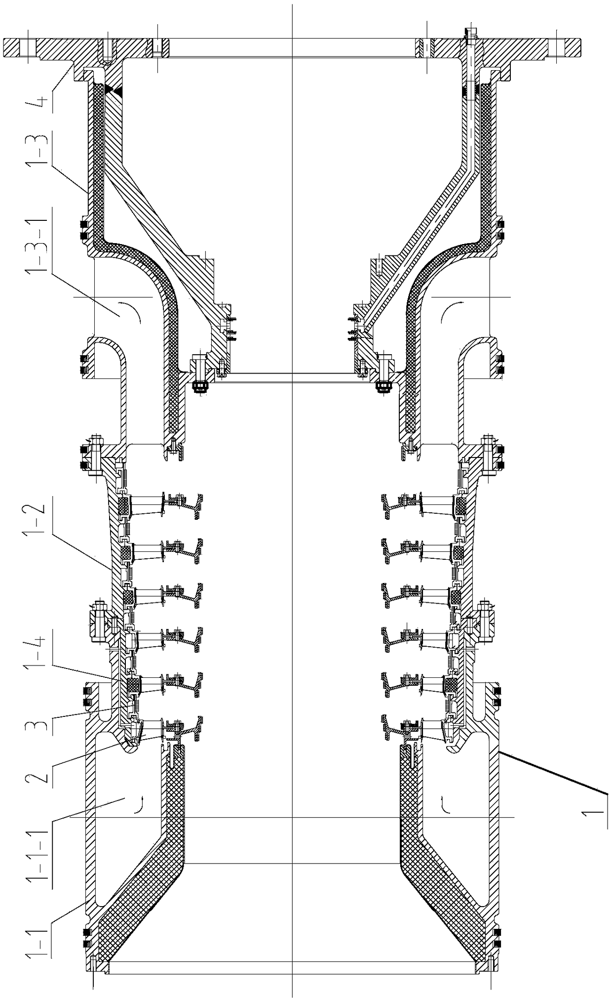
[0020] Specific implementation mode one: combine figure 1 Describe this embodiment, the turbine stator structure for helium gas turbine described in this embodiment includes a turbine casing 1, a guide 2, a sealing guard ring 3 and a bearing housing 4, and the bearing housing 4 extends into the The tail of the turbine casing 1 is fixedly connected, and the seal retaining ring 3 and multiple sets of guides 2 are fixed in the card slot inside the turbine casing 1;

[0021] The turbine case includes an intake case 1-1, a turbine case 1-2 and an exhaust case 1-3, and the front and rear ends of the intake case 1-1 and the turbine case 1-2 are Flanges are respectively provided. The front end of the exhaust casing 1-3 and the upper middle of the interior are respectively provided with flanges. The front end of the bearing housing 4 is provided with a flange, and the rear end is provided with a clip groove;

[0022] The flange at the rear end of the intake casing 1-1 and the flange ...

specific Embodiment approach 2

[0026] Specific implementation mode two: combination figure 1 , 2 and 4 illustrate this embodiment,

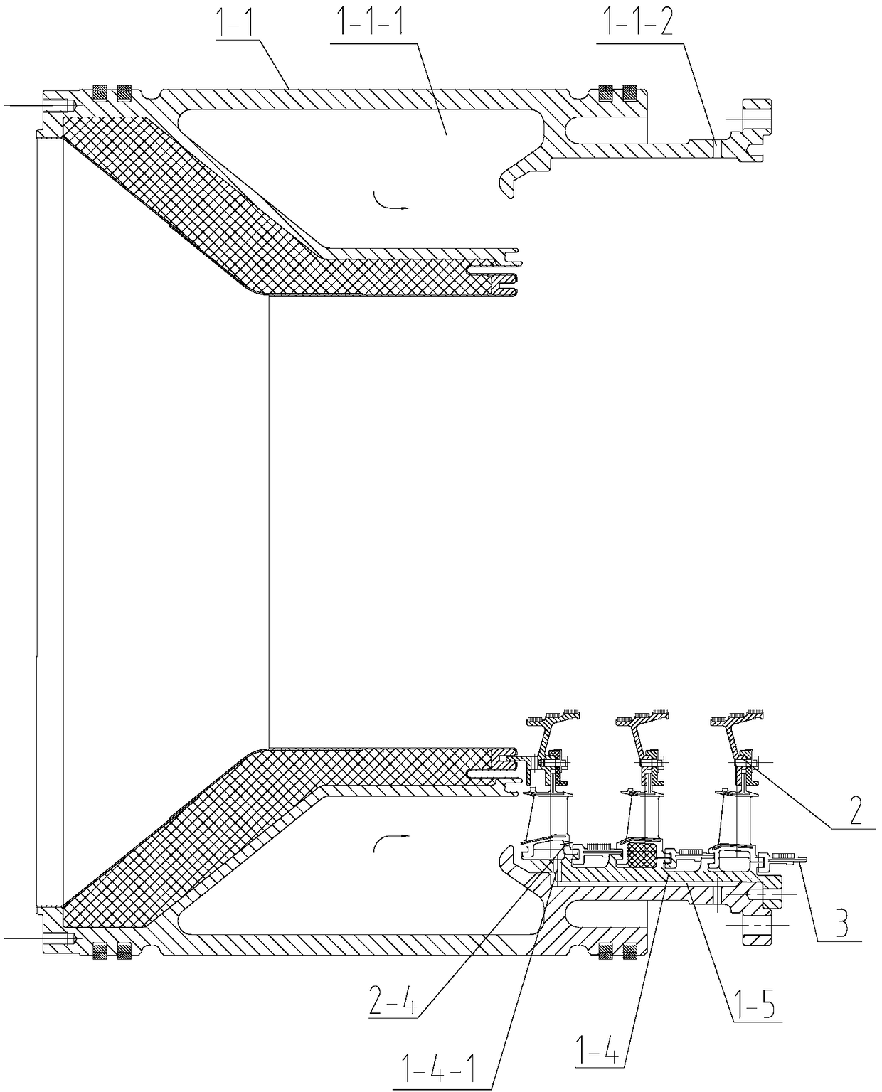
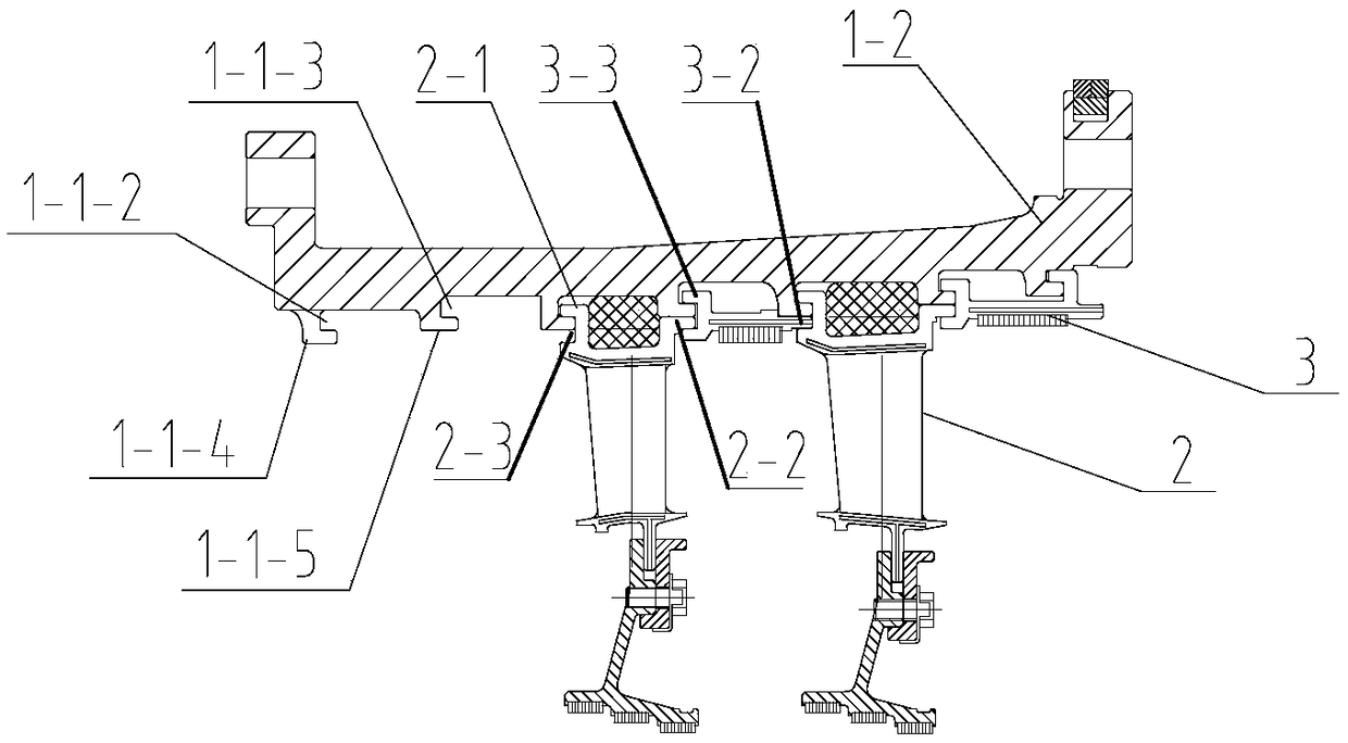
[0027] Such as figure 2 As shown: an inner casing 1-4 is also arranged inside the air intake casing 1-1, and the front 3-stage guide group and the front 3-stage sealing guard ring 3 are installed alternately in the inner casing 1 -4 in the card slot, and fixed inside the intake casing 1-1 through the inner casing 1-4;

[0028] Such as Figure 4 Shown: the tail end of the inner casing 1-4 has a flange; as figure 2 As shown: the tail end of the intake casing 1-1 has a pin hole, the front end of the inner casing 1-4 is stuck in the card slot in the intake casing 1-1, and the flange at the tail end is fixed on the intake casing by pins. In the pin hole at the tail end of the air casing 1-1;

[0029] Such as figure 2 As shown: the fourth cooling gas passage 1-5 is formed between the air intake casing 1-1 and the inner casing 1-4.

[0030] The inner casing is arranged in ...

specific Embodiment approach 3

[0032] Specific implementation mode three: as figure 2 with Figure 5 As shown: the air intake casing 1-1 described in this embodiment also has two air intake holes, and the air intake holes are connected with the air intake channel 1- 1-1 communicate; the exhaust casing 1-3 is provided with an exhaust passage 1-3-1 in the circumferential direction.

[0033] The high-temperature helium gas enters the air intake channel through the air intake hole, guides the flow through the guide set, and then acts on the moving blades of the rotor.

[0034] Other compositions and connection methods are the same as those in Embodiment 1 or 2.


PUM


Abstract

The invention provides a turbine stator structure for a helium turbine, relates to the field of turbines, and solves the problems that when a conventional turbine is applied to a nuclear reactor, an entire turbine case is integrated and inconvenient to dismount and mount, an entire turbine stator structure is too long, and the helium work efficiency is low. The turbine stator structure comprises agas intake machine case, a turbine case, a gas exhauster case, guides, sealing rings and a bearing shell, wherein a flange at the rear end of the gas intake machine case and a flange at the front endof the turbine case are in bolted connection with each other; a flange at the rear end of the turbine case and a flange at the front end of the gas exhauster case are in bolted connection with each other; a flange at the front end of the bearing shell and a flange at a position above the inner middle of the gas exhauster case are in bolted connection with each other; the rear end of the gas exhauster case is inserted into a clamping slot at the tail of the bearing shell; and the guide groups of six grades and the sealing rings of six grades are sequentially mounted in the gas exhauster case and the clamping slot of the gas exhauster case one by one. The turbine stator structure provided by the invention is applied to the helium turbine.

Description

technical field [0001] The invention relates to the field of turbines, in particular to a turbine stator structure for a helium turbine. Background technique [0002] The existing turbine stator structure is not suitable for the work of the helium turbine. The existing turbine is applied to the nuclear reactor and the entire turbine case is integrated, which is not easy to disassemble; and the overall length of the turbine stator structure makes the helium in the nuclear reactor The initial temperature of the gas entering the turbine and acting on the moving blades is low, and the work efficiency of helium is low, which cannot meet the performance requirements of the aerodynamic design. Contents of the invention [0003] The technical problem to be solved by the present invention is: the existing turbine is applied to the nuclear reactor and the entire turbine casing is integrated, which is not easy to disassemble; and the overall structure of the turbine stator is too lon...

Claims


Application Information

Patent Timeline
Patent Type & Authority Applications(China)
IPC IPC(8): F01D9/04F01D25/28
CPCF01D9/041F01D9/042F01D25/28
Inventor 郁顺旺刘勋舒春英张馨马涛朱凯迪
Owner 中国船舶重工集团公司第七0三研究所
Why Eureka
Try Eureka