
Sliding vane structure, pump body assembly and compressor

A technology of compressors and sliding vanes, which is applied to pump components, liquid fuel engines, components of pumping devices for elastic fluids, etc., can solve the problems of difficult processing of sliding vanes, improve user experience, reduce noise, Effect of improving connection stability

Pending Publication Date: 2018-12-21
ZHUHAI GREE REFRIGERATION TECH CENT OF ENERGY SAVING & ENVIRONMENTAL PROTECTION
View PDF0 Cites 0 Cited by
  • Summary
  • Abstract
  • Description
  • Claims
  • Application Information

AI Technical Summary

Problems solved by technology

[0004] The main purpose of the present invention is to provide a sliding vane structure, a pump body assembly and a compressor, so as to solve the problem that the sliding vanes in the prior art are difficult to process

Method used

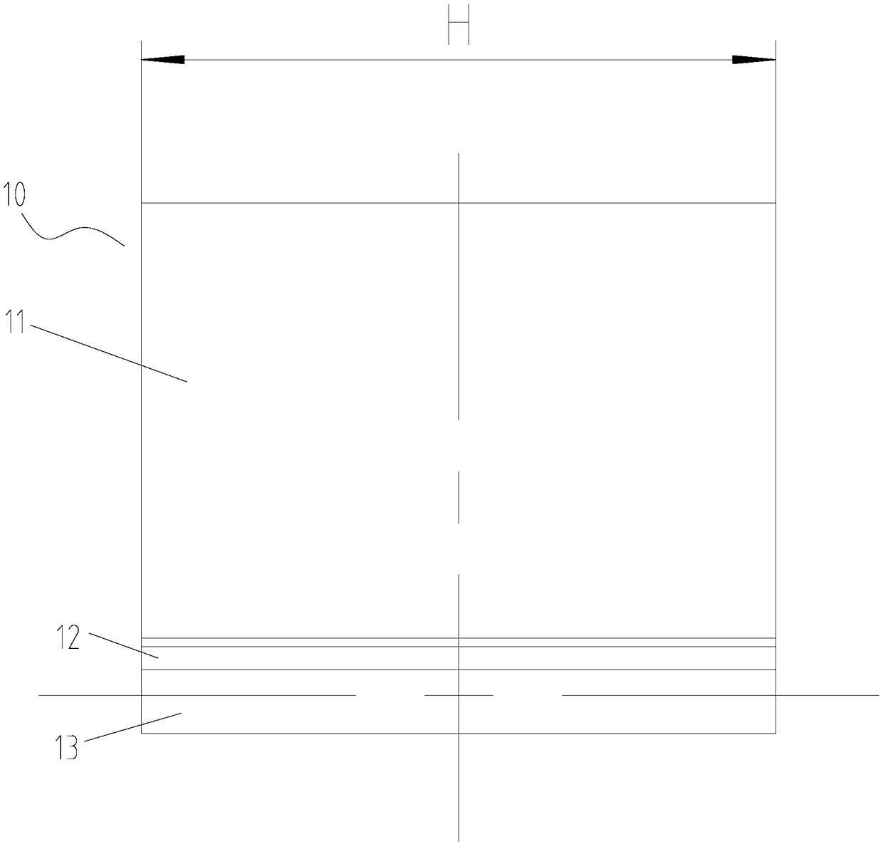
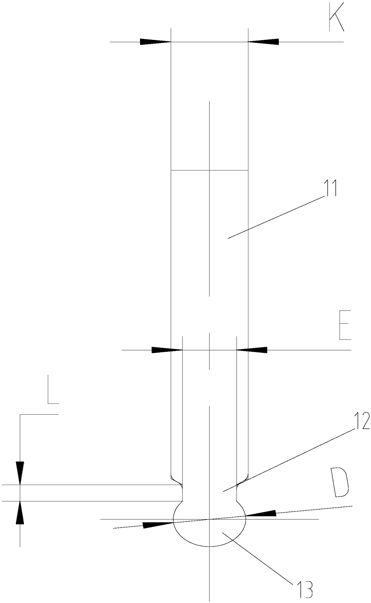
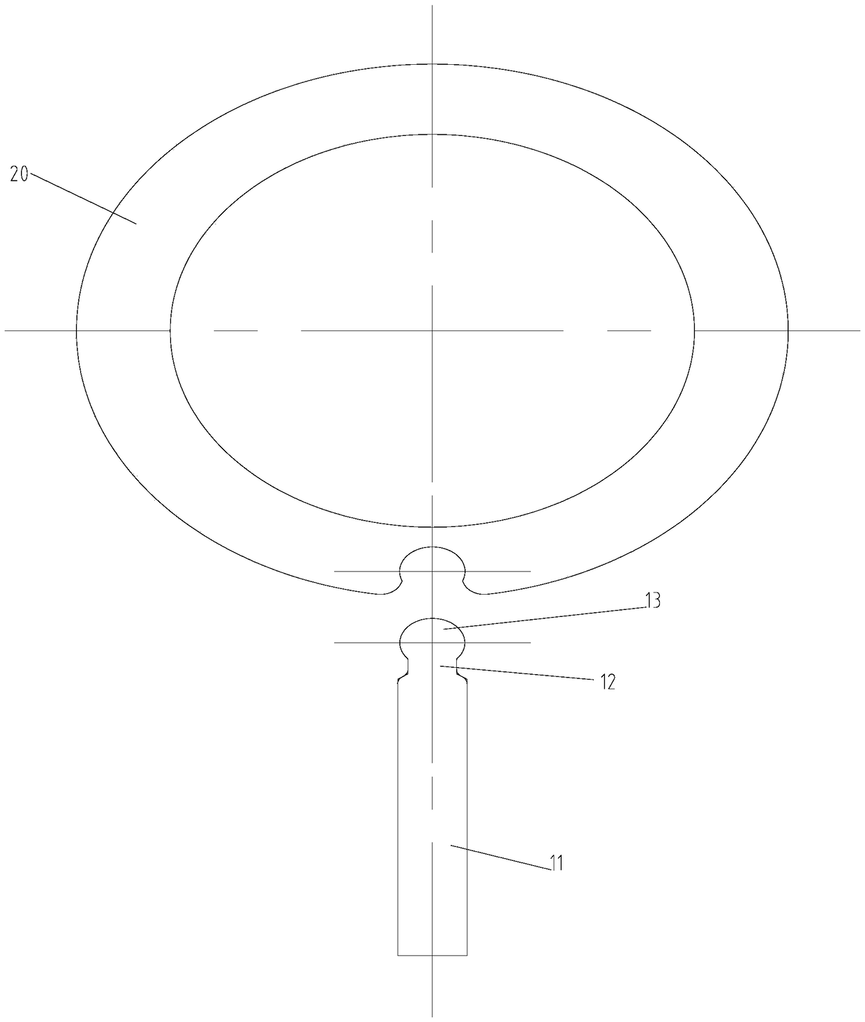

Image

  • Sliding vane structure, pump body assembly and compressor
  • Sliding vane structure, pump body assembly and compressor
  • Sliding vane structure, pump body assembly and compressor

Examples


Embodiment Construction

[0024] It should be noted that, in the case of no conflict, the embodiments in the present application and the features in the embodiments can be combined with each other. The present invention will be described in detail below with reference to the accompanying drawings and examples.

[0025] It should be noted that the terminology used here is only for describing specific implementations, and is not intended to limit the exemplary implementations according to the present application. As used herein, unless the context clearly dictates otherwise, the singular is intended to include the plural, and it should also be understood that when the terms "comprising" and / or "comprising" are used in this specification, they mean There are features, steps, operations, means, components and / or combinations thereof.

[0026] It should be noted that the terms "first" and "second" in the specification, claims and drawings of the present application are used to distinguish similar objects, ...


PUM


Abstract

The invention provides a sliding vane structure, a pump body assembly and a compressor. The sliding vane structure comprises a sliding vane body, wherein the sliding vane body is provided with a mounting end and a connecting end, and the connecting end is used for connecting with rollers; and the connecting end is of a columnar structure, the outer diameter of the columnar structure is D, and theD / H ratio is greater than or equal to 1 and less than or equal to 8, wherein the H is the width of the sliding vane body. According to the arrangement of the sliding vane structure, the processing difficulty of a sliding vane can be reduced, and the connection stability of the sliding vane and the roller is improved. The sliding vane with the structure can prevent the compressor from generating liquid impact, effectively reduce the noise of the compressor and improve the use experience of users.

Description

technical field [0001] The invention relates to the technical field of compressor equipment, in particular to a sliding vane structure, a pump body assembly and a compressor. Background technique [0002] The sliding vanes and rollers of the existing rolling rotor compressors press the sliding vanes against the rollers through spring force. This structure will cause liquid shock when the compressor is sucked with liquid, and the liquid shock will cause sliding. If the disc and the roller are separated, on the one hand, it will cause high and low pressure gas, and the cooling capacity of the compressor will drop significantly. On the other hand, after the sliding vane is separated from the roller, it will withstand the roller again under the action of the spring force, and the moment the sliding vane head touches the roller, it will collide with the roller to generate noise. [0003] In the prior art, a hole larger than a semicircle is opened on the roller, and a cylindrical...

Claims


Application Information

Patent Timeline
Patent Type & Authority Applications(China)
IPC IPC(8): F04C29/00F04C18/356
CPCF04C18/3562F04C29/00F04C2240/20
Inventor 彭慧明赵旭敏樊峰刚张洪玮卢林高
Owner ZHUHAI GREE REFRIGERATION TECH CENT OF ENERGY SAVING & ENVIRONMENTAL PROTECTION
Learn More