

Image generation method and apparatus based on 3D rendering engine
A rendering engine and image generation technology, which is applied in the field of image processing, can solve problems such as difficult modeling and unfriendly user-defined models, and achieve the effect of breaking through computing limitations and facilitating modeling
- Summary
- Abstract
- Description
- Claims
- Application Information
AI Technical Summary
Problems solved by technology
Method used
Image

Examples
no. 1 example
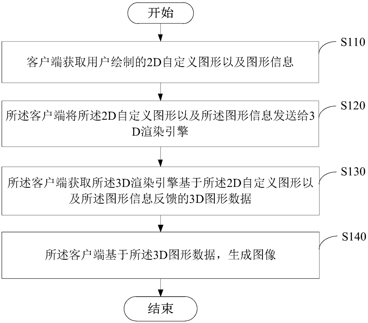
[0029] Please refer to image 3 , image 3 It is a flow chart of an image generation method based on a 3D rendering engine provided by the first embodiment of the present invention, and the method is applied to a client, such as an image client installed in an electronic device. Wherein, the image can be applied to a background wall, a suspended ceiling, a platform, and the like.
[0030] The following will generate background wall image pairs image 3 The process shown is described in detail, and the method includes:
[0031]Step S110: the client acquires the 2D custom graphics and graphic information drawn by the user.
[0032] Optionally, the client may include a 2D wall interface, a 2D house type interface, a 3D house type interface, and a rendering engine data construction window.
[0033] Users can freely draw the 2D plane graphics they need in the 2D wall interface of the client, and input the required raised height of the background wall in the rendering engine dat...
no. 2 example
[0049] Please refer to Figure 4 , Figure 4 It is a flow chart of an image generation method based on a 3D rendering engine provided by the first embodiment of the present invention, and the method is applied to a 3D rendering engine, such as a ThreeJS engine. Of course, the ThreeJS engine is only an example, and the 3D rendering engine described in the embodiment of the present invention may also be any other 3D rendering engine. The following will take the ThreeJS engine as an example, for Figure 4 The process shown is described in detail, and the method includes:
[0050] Step S210: the 3D rendering engine acquires the 2D custom graphics and the graphics information sent by the client.
[0051] Step S220: The 3D rendering engine generates 3D graphic data based on the 2D custom graphic and the graphic information, and feeds it back to the client, so that the client generates an image based on the 3D graphic data.
[0052] The graphics information includes the coordinat...
no. 3 example
[0056] Please refer to Figure 5 , Figure 5 It is a structural block diagram of an image generation device 400 based on a 3D rendering engine provided by the third embodiment of the present invention. The following will be Figure 5 The structure block diagram shown is described, and the shown device includes:
[0057] An image capture module 410, configured to acquire 2D custom graphics and graphic information drawn by the user;
[0058] A sending module 420, configured to send the 2D custom graphics and the graphics information to a 3D rendering engine;
[0059] An acquisition module 430, configured to acquire 3D graphics data fed back by the 3D rendering engine based on the 2D custom graphics and the graphics information;
[0060] The rendering module 440 is configured to generate an image based on the 3D graphic data.
[0061] In this embodiment, for the process of realizing respective functions of each functional module of the image generation device 400 based on th...
PUM
 Abstract
Description
Claims
Application Information