
Connector

A connector and contact technology, which is applied in the direction of connection, two-part connection device, and parts of the connection device, etc., can solve the problems of affecting the stable operation of electronic equipment, difficult insertion and removal, and increased insertion force.

Inactive Publication Date: 2018-12-21
ZHENGZHOU YUNHAI INFORMATION TECH CO LTD
View PDF5 Cites 1 Cited by
  • Summary
  • Abstract
  • Description
  • Claims
  • Application Information

AI Technical Summary

Problems solved by technology

In order to ensure that the power consumption of each functional component in the server is sufficient, it is necessary to add multiple sets of mating male ends and female ends in the connector, which leads to a continuous increase in the number of mating male ends and female ends in the connector. Increase, it is used to overcome the friction force generated at a certain moment when most male ends enter the corresponding female end at the same time, and naturally the insertion force of plugging and unplugging the male end relative to the female end also increases accordingly. It is difficult to plug and unplug, and it is inconvenient to plug and unplug
[0004] Furthermore, when the insertion force is too large, the PCB board where the female terminal is located may be deformed, which will affect the stable operation of the electronic equipment, and the reliability is low
[0005] Therefore, the existing connectors are inconvenient to plug and unplug and have low reliability

Method used


Image

  • Connector
  • Connector
  • Connector

Examples


Embodiment Construction

[0030] The following will clearly and completely describe the technical solutions in the embodiments of the present invention with reference to the accompanying drawings in the embodiments of the present invention. Obviously, the described embodiments are only some, not all, embodiments of the present invention. Based on the embodiments of the present invention, all other embodiments obtained by persons of ordinary skill in the art without making creative efforts belong to the protection scope of the present invention.

[0031] In order to enable those skilled in the art to better understand the solution of the present invention, the present invention will be further described in detail below in conjunction with the accompanying drawings and specific embodiments.

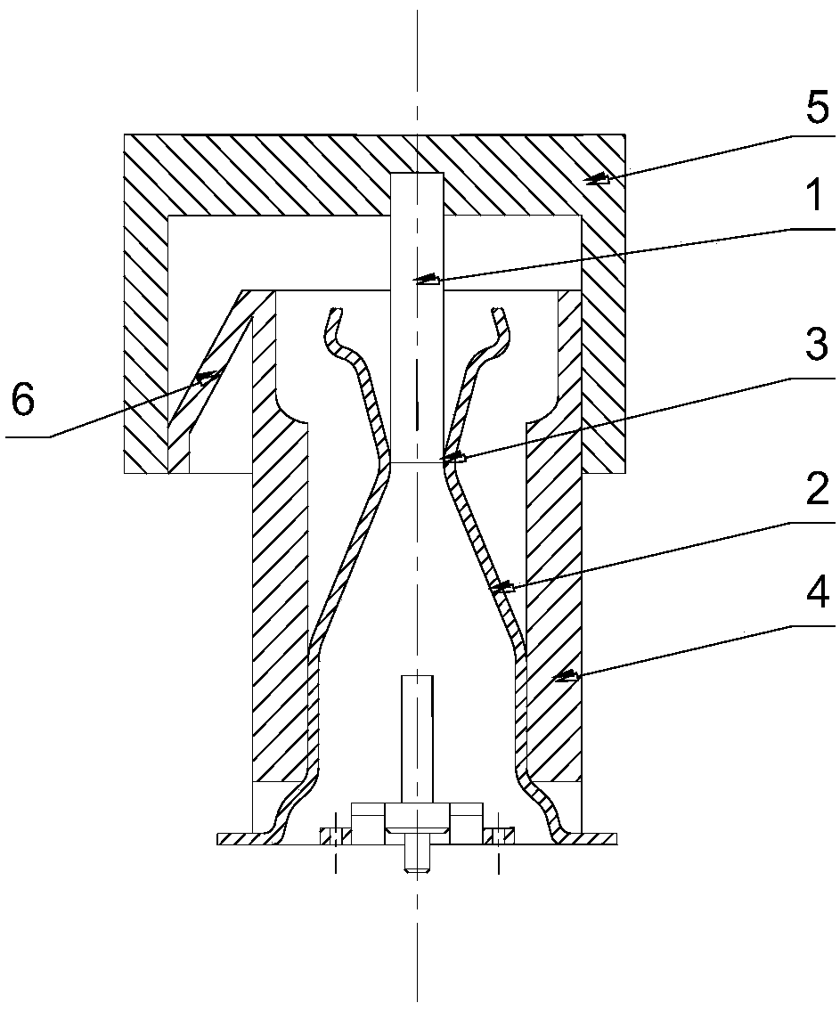
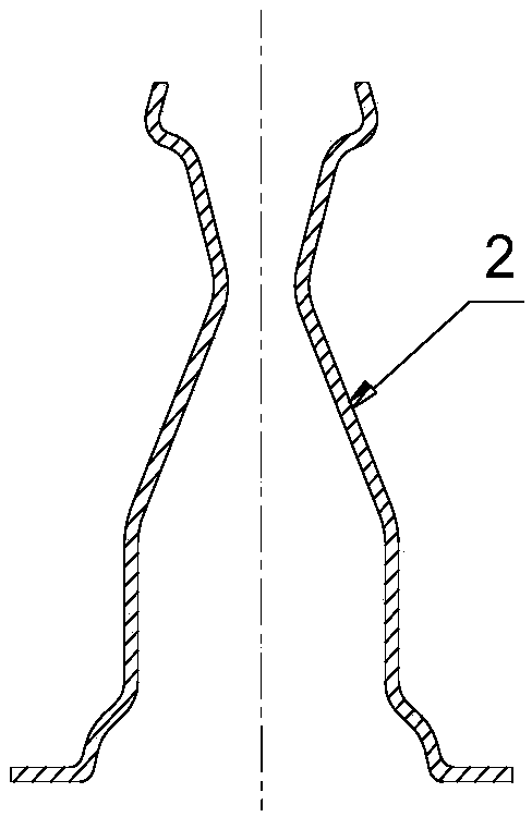
[0032] Please refer to Figure 1 to Figure 5 , figure 1 A cross-sectional structure diagram of a connector provided for a specific embodiment of the present invention; figure 2 for figure 1 The front section vie...


PUM


Abstract

A connector includes a plurality of male end heads and a plurality of female end heads respectively matched with the plurality of male end heads, wherein each female end head is provided with an elastic engaging portion for abutting with the male end head to clamp the male end head for realizing signal communication, and any two adjacent elastic engaging portions are respectively contacted with the corresponding male end head in succession. When the male end enters the female end, the male end is contacted with a part of the elastic engaging part at different times, so as to avoid that a plurality of male ends contact with the elastic engaging portion of the female end at the same time, and the total frictional resistance between the plurality of male ends and the elastic engaging portionat a certain time is reduced compared with the total frictional group force in the prior art, so that the insertion force for inserting and pulling the plurality of male ends is reduced, and the insertion and pulling difficulty is small and the insertion and pulling are easy; With the decrease of insertion and withdrawal force, the risk of PCB deformation is reduced, which makes the PCB work stably and reliably. Therefore, the connector provided by the invention is easy to plug and unplug and has high reliability.

Description

technical field [0001] The invention relates to the technical field of electronic engineering, in particular to a connector. Background technique [0002] As one of the indispensable key components in electronic equipment, connectors are usually used to block or connect current, light waves and radio signals between related components in electronic equipment, and are widely used in electronic equipment in various fields. [0003] Existing connectors include several sets of male and female terminals that cooperate with each other. When each set of male terminals is inserted into the corresponding female terminal, a certain friction force must be ensured to ensure that the female terminal can be connected with the male terminal. Stable connection. Taking the connector in the server as an example, the existing server usually includes a motherboard and various auxiliary components, wherein the motherboard includes a BIOS chip, an I / O control chip, keys and panel control switch ...

Claims


Application Information

Patent Timeline
IPC IPC(8): H01R13/11H01R13/629H01R13/631H01R24/00
CPCH01R13/11H01R13/629H01R13/631H01R24/005
Inventor 刘世正王晓澎
Owner ZHENGZHOU YUNHAI INFORMATION TECH CO LTD
Learn More