Motors, wheels and electric vehicles capable of displaying patterns or characters
A technology for displaying patterns and characters, applied in the direction of electric components, electrical components, electromechanical devices, etc., can solve the problems of no lighting effect, single display, no safety prompt function, etc. Effect
- Summary
- Abstract
- Description
- Claims
- Application Information
AI Technical Summary
Problems solved by technology
Method used
Image
Examples
Embodiment 1
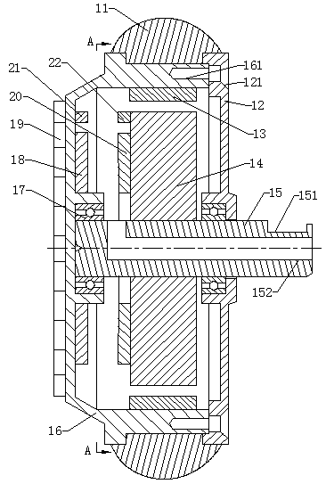
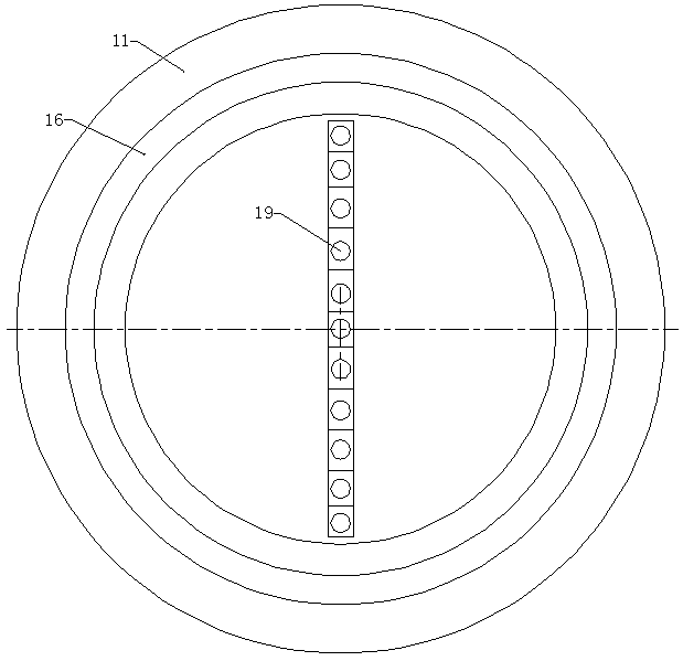
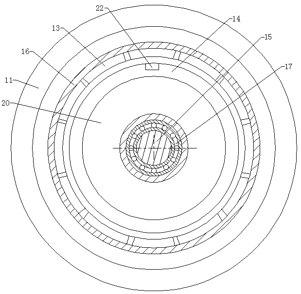
[0035] A motor that can display patterns or text, see Figure 1 to Figure 3, including a stator 14, a front end cover 16, a rear end cover 12, a rotor magnetic steel 13, a first induction coil 18, a second induction coil 20, an LED light bar 19, a sensing unit and a wheel shaft 15, the wheel shaft 15 is a fixed shaft, and the rear The end cover 12 is installed on the rear end of the wheel shaft 15 through a bearing, the rear end of the wheel shaft 15 passes through the rear end cover 12, and the rear end cover 12 is provided with a through hole for the wheel shaft 15 to pass through at the corresponding position, that is, the wheel shaft 15 is sleeved Bearing, the outer surface of the wheel shaft 15 is interference-connected to the inner surface of the bearing inner ring, the outer surface of the bearing outer ring is sleeved with a rear end cover 12, the outer surface of the bearing outer ring is interference-connected to the rear end cover 12, and the rear end cover 12 is set...
Embodiment 2
[0051] For this example, see Figure 4 , the front end cover 16 is a transparent part, which can transmit light to the LED light beads on the LED light bar, the LED light bar 19 is glued to the inner surface of the front end cover 16, and the first induction coil 18 is glued to the circuit board of the LED light bar. On the inside surface, the receiving device 21 is also glued to the inside surface of the circuit board of the LED light bar. The height of the first induction coil is as described in Embodiment 1, which is aligned with the height of the second induction coil. Other structures and principles are as described in the embodiment 1 and will not be repeated here.
Embodiment 3
[0053] see Image 6 , in this embodiment, the front end cover 16 is a transparent part, which can transmit light to the LED light beads on the LED light bar, the LED light bar 19 is glued on the inner surface of the front end cover 16, and the first induction coil 18 is glued on the LED lamp The inner side surface of the circuit board of the strip, the front cover 16 is not directly connected to the wheel shaft 15, and the bearing between the two is canceled. This design allows the LED light bar to pass through the rotation center of the front cover 16 and extend to the edge of the front cover , to ensure that the pattern and size to be displayed are maximized, while the rear end cover 12 is installed on the wheel shaft 15 through the bearing 17, and the front end cover 16 is connected with the rear end cover 12 by fasteners. Other structures and principles are as described in Embodiment 1 and will not be repeated here.
PUM
 Abstract
Description
Claims
Application Information
 - R&D
- Intellectual Property
- Life Sciences
- Materials
- Tech Scout
- Unparalleled Data Quality
- Higher Quality Content
- 60% Fewer Hallucinations
Browse by: Latest US Patents, China's latest patents, Technical Efficacy Thesaurus, Application Domain, Technology Topic, Popular Technical Reports.
© 2025 PatSnap. All rights reserved.Legal|Privacy policy|Modern Slavery Act Transparency Statement|Sitemap|About US| Contact US: help@patsnap.com


