A Hall signal amplify circuit

A technique for amplifying circuits and Hall signals, applied in amplifiers, differential amplifiers, improving amplifiers to reduce temperature/power supply voltage changes, etc., can solve the problem of affecting applications, not having a good temperature compensation effect, and not completely eliminating the offset voltage of operational amplifiers, etc. question

Pending Publication Date: 2018-12-21
BCD (SHANGHAI) MICRO ELECTRONICS LTD
View PDF8 Cites 6 Cited by
  • Summary
  • Abstract
  • Description
  • Claims
  • Application Information

AI Technical Summary

Problems solved by technology

[0002] In the process of amplifying the Hall signal, affected by the offset voltage of the operational amplifier, the static output voltage (in the case of zero magnetic field) is not at the midpoint potential, which affects its application in high-precision speed detection sensors and position detection sensors
In order to reduce the influence of the offset voltage of the operational amplifier, the traditional Hall signal amplifier circuit generally adopts the reference figure 1 The instrumentation amplifier structure shown includes the Hall sensor module 01 for outputting the Hall signal, the first operational amplifier OPA 1 , the second operational amplifier OPA 2 , the third operational amplifier OPA 3 , the first resistor, the second resistor until the seventh resistor, where the first resistor is denoted as R 0 , the second resistor is the same as the third resistor, both are denoted as R 01 , the fourth resistor and the fifth resistor are the same, both are denoted as R 02 , the sixth resistor and the seventh resistor are the same, both are denoted as R 03 , although this symmetrical structure can reduce the influence of the offset voltage of the op amp to a certain extent, it cannot completely eliminate the offset voltage of the op amp.
In order to achieve the effect of offsetting the offset voltage of the operational amplifier, the Hall signal amplifying circuit also includes an adjustment module 02 on the basis of this structure, which is used to adjust the reference voltage V REF , so as to offset the influence of the offset voltage of the op amp, but the offset voltage of the op amp in the Hall signal amplifying circuit will also change with the temperature, considering the temperature coefficient of the offset voltage of the op amp and the thermal voltage V in the amplifying circuit T It is difficult to offset by the temperature coefficient of a single resistor. Therefore, the solution in the prior art does not have a good temperature compensation effect on the offset voltage of the op amp in the Hall amplifier circuit, and cannot guarantee that the static output voltage is in the full temperature operating range. high precision in

Method used


Image

  • A Hall signal amplify circuit
  • A Hall signal amplify circuit
  • A Hall signal amplify circuit

Examples


Embodiment Construction

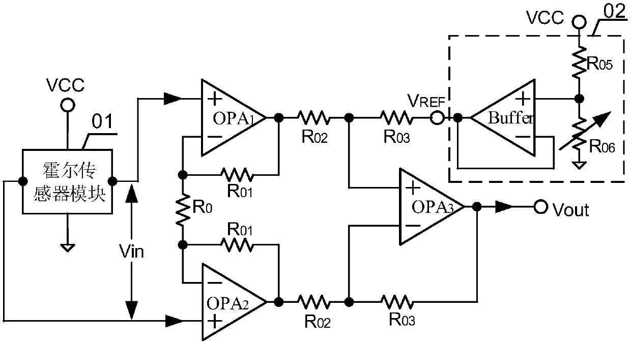
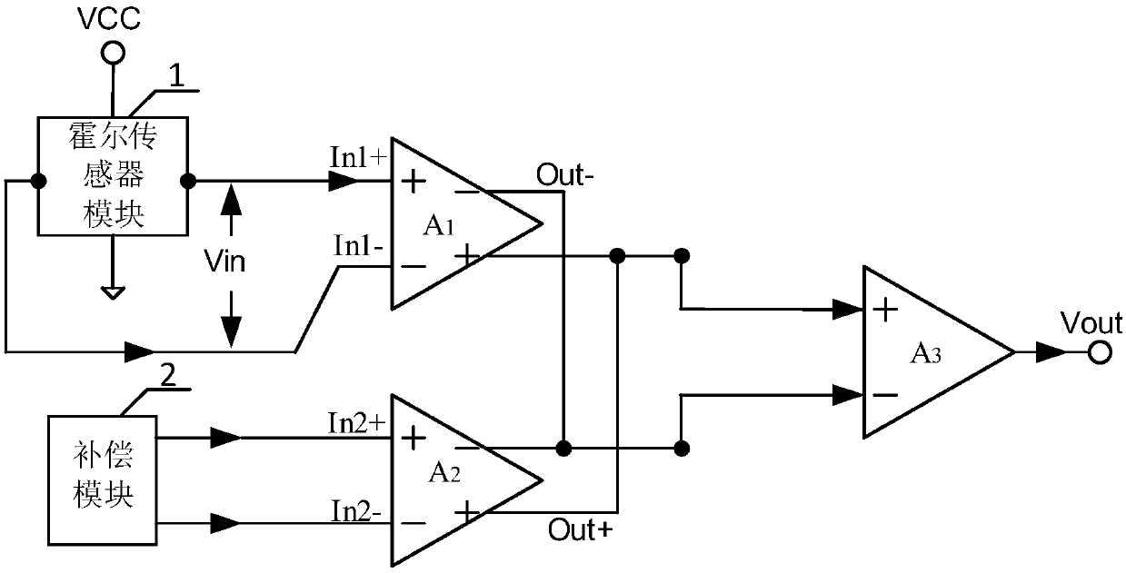
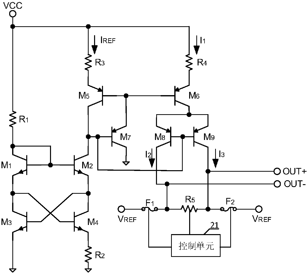
[0033] The core of the present invention is to provide a Hall signal amplifying circuit, which generates an equivalent input offset voltage related to thermal voltage through the compensation module. It has high accuracy in the whole temperature working range.

[0034] In order to make the purpose, technical solutions and advantages of the embodiments of the present invention clearer, the technical solutions in the embodiments of the present invention will be clearly and completely described below in conjunction with the drawings in the embodiments of the present invention. Obviously, the described embodiments It is a part of embodiments of the present invention, but not all embodiments. Based on the embodiments of the present invention, all other embodiments obtained by persons of ordinary skill in the art without making creative efforts belong to the protection scope of the present invention.

[0035] Please refer to figure 2 , figure 2 It is a structural schematic diag...


PUM


Abstract

A Hall signal amplify circuit includes a Hall sensor module connected to a power supply, first amplifier, second amplifier, third amplifier, compensation module, a first output of the Hall sensor module is connected to a non-inverting input of the first amplifier, a second output of the Hall sensor module is connected to an inverting input of the first amplifier, the non-inverting output terminalof the first amplifier is respectively connected with the non-inverting output terminal of the second amplifier and the non-inverting input terminal of the third amplifier. The inverting output terminal of the first amplifier is respectively connected with the inverting output terminal of the second amplifier and the inverting input terminal of the third amplifier, the first output terminal of thecompensation module is connected with the non-inverting input terminal of the second amplifier, and the second output terminal of the compensation module is connected with the inverting input terminal of the second amplifier. The invention generates the equivalent input offset voltage related to the thermal voltage through the compensation module, and has good temperature compensation function while eliminating the operational amplifier offset voltage.

Description

technical field [0001] The invention relates to the field of amplifiers, in particular to a Hall signal amplifying circuit. Background technique [0002] In the process of amplifying the Hall signal, affected by the offset voltage of the operational amplifier, the static output voltage (in the case of zero magnetic field) is not at the midpoint potential, which affects its application in high-precision speed detection sensors and position detection sensors. In order to reduce the influence of the offset voltage of the operational amplifier, the traditional Hall signal amplifier circuit generally adopts the reference figure 1 The instrumentation amplifier structure shown includes the Hall sensor module 01 for outputting the Hall signal, the first operational amplifier OPA 1 , the second operational amplifier OPA 2 , the third operational amplifier OPA 3 , the first resistor, the second resistor until the seventh resistor, where the first resistor is denoted as R 0 , the s...

Claims


Application Information

Patent Timeline
Patent Type & Authority Applications(China)
IPC IPC(8): H03F1/30H03F3/42H03F3/45
CPCH03F1/30H03F3/42H03F3/4508H03F2203/45026H03F2203/45031
Inventor 张旭光孙炜胡金玺
Owner BCD (SHANGHAI) MICRO ELECTRONICS LTD
Why Eureka
Try Eureka