Air purifier
An air purifier and inner cavity technology, applied in the field of air purification, can solve the problems of high cost, complex structure of the purifier, low efficiency of purifying PM2.5, etc.
- Summary
- Abstract
- Description
- Claims
- Application Information
AI Technical Summary
Problems solved by technology
Method used
Image
Examples
Embodiment 1
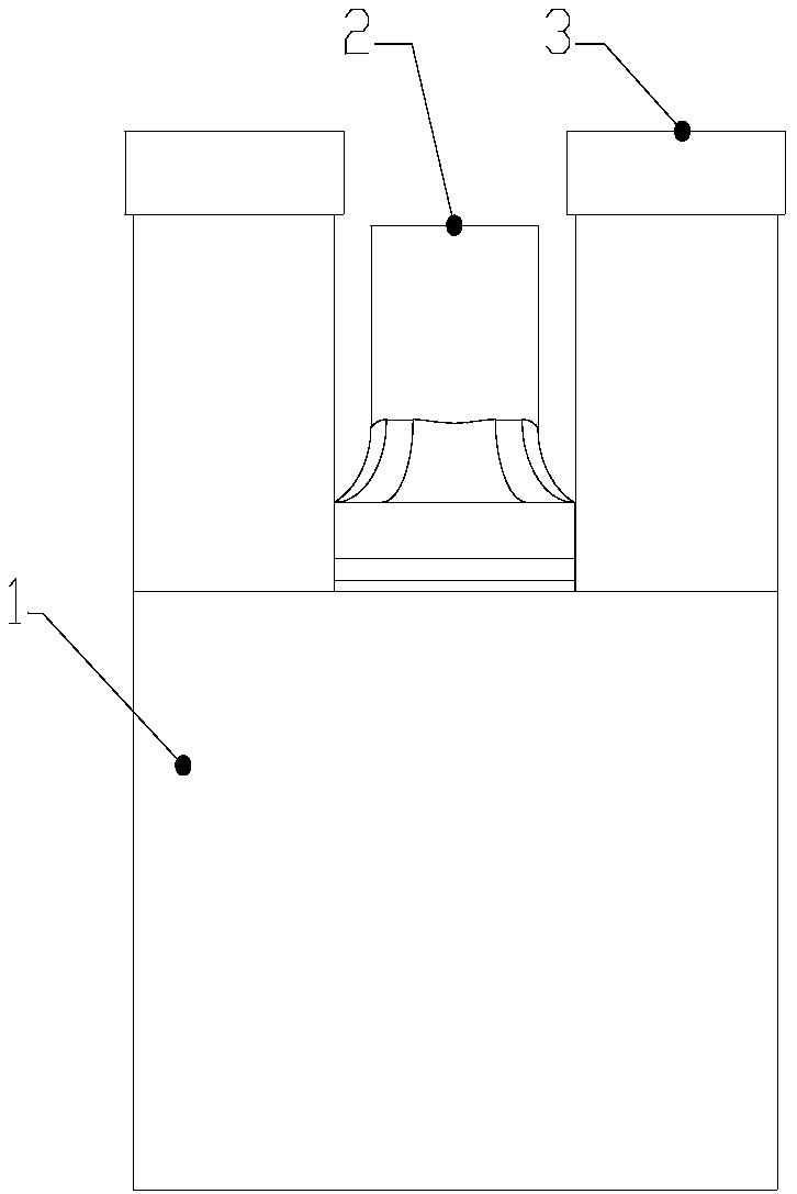
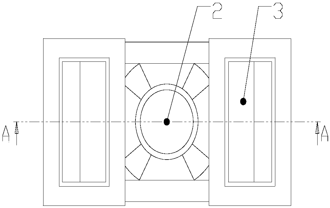
[0035] Such as figure 1 and figure 2 As shown in , an air purifier according to a preferred embodiment of the present invention includes a housing 1 with an inner cavity, and the top wall of the inner cavity of the housing 1 is provided with an air inlet 2 and an air outlet 3 for respectively The air to be filtered and purified is introduced and the purified air is sent out, and a water tank 4 is formed at the bottom of the inner cavity.
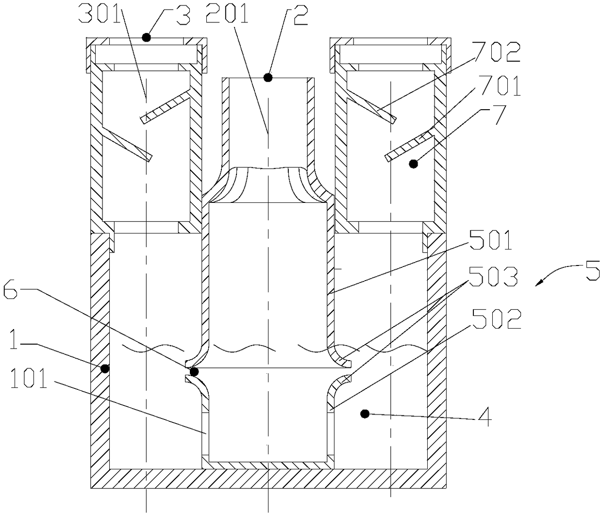
[0036] refer to image 3 As shown, the inner cavity is provided with a partition wall 5 that separates the inner cavity into an air inlet channel 201 and an air outlet channel 301 , and the partition wall 5 extends from between the air inlet 2 and the air outlet 3 to the bottom wall of the water tank 4 . The partition wall 5 is divided into an upper partition wall 501 extending from the top wall of the inner cavity to the direction of the water tank 4 and a lower partition wall 502 extending from the bottom wall of the water tank 4 to the...
Embodiment 2
[0043] Such as Figure 5 As shown in , the air purifier according to another preferred embodiment of the present invention differs from that of Embodiment 1 in that an arc-shaped upper deflector 504 and a lower deflector are arranged on one side of the air outlet passage 301 The flow plate 505, the lower flow guide plate 505 bends upwards from the end of the arc wall 503 on the lower partition wall 502, and the upper flow guide plate 504 bends downward from the end of the arc wall 503 on the upper partition wall 501. The baffles 504 are arranged above the lower baffle 505 at intervals and form a vortex chamber 8 between the upper and lower baffles, and a vortex chamber 8 is formed between the extension end of the upper baffle 504 and the extension end of the lower baffle 505 toward the air outlet. The diversion outlet 801 of the liquid level of the water tank 4 in the channel 301 .
[0044] Such as Figure 6 and Figure 7 As shown in , the high-speed airflow ejected from th...
PUM
 Abstract
Description
Claims
Application Information
 - R&D
- Intellectual Property
- Life Sciences
- Materials
- Tech Scout
- Unparalleled Data Quality
- Higher Quality Content
- 60% Fewer Hallucinations
Browse by: Latest US Patents, China's latest patents, Technical Efficacy Thesaurus, Application Domain, Technology Topic, Popular Technical Reports.
© 2025 PatSnap. All rights reserved.Legal|Privacy policy|Modern Slavery Act Transparency Statement|Sitemap|About US| Contact US: help@patsnap.com


