
Three-wire gas shielded indirect arc welding method, device and application of method

A gas shielded, arc welding technology, applied in arc welding equipment, welding/welding/cutting items, welding equipment, etc., can solve the problem of two indirect arc tail deflection, etc., to improve arc stiffness, optimize the spatial distribution of magnetic field, workpiece The effect of increased heat input

Active Publication Date: 2018-12-25
DALIAN UNIV OF TECH
View PDF5 Cites 13 Cited by
  • Summary
  • Abstract
  • Description
  • Claims
  • Application Information

AI Technical Summary

Problems solved by technology

[0011] According to the above-mentioned technical problems that the arcs in the existing three-wire indirect arc welding method are deflected to both sides respectively, a three-wire gas-shielded indirect arc welding method, device and application thereof are provided
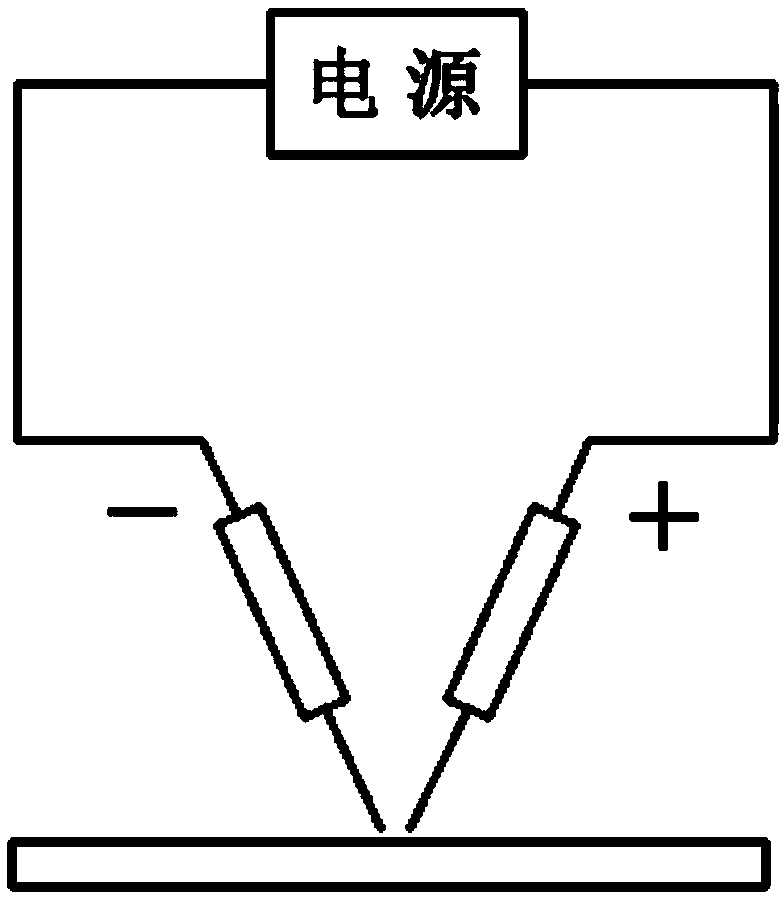
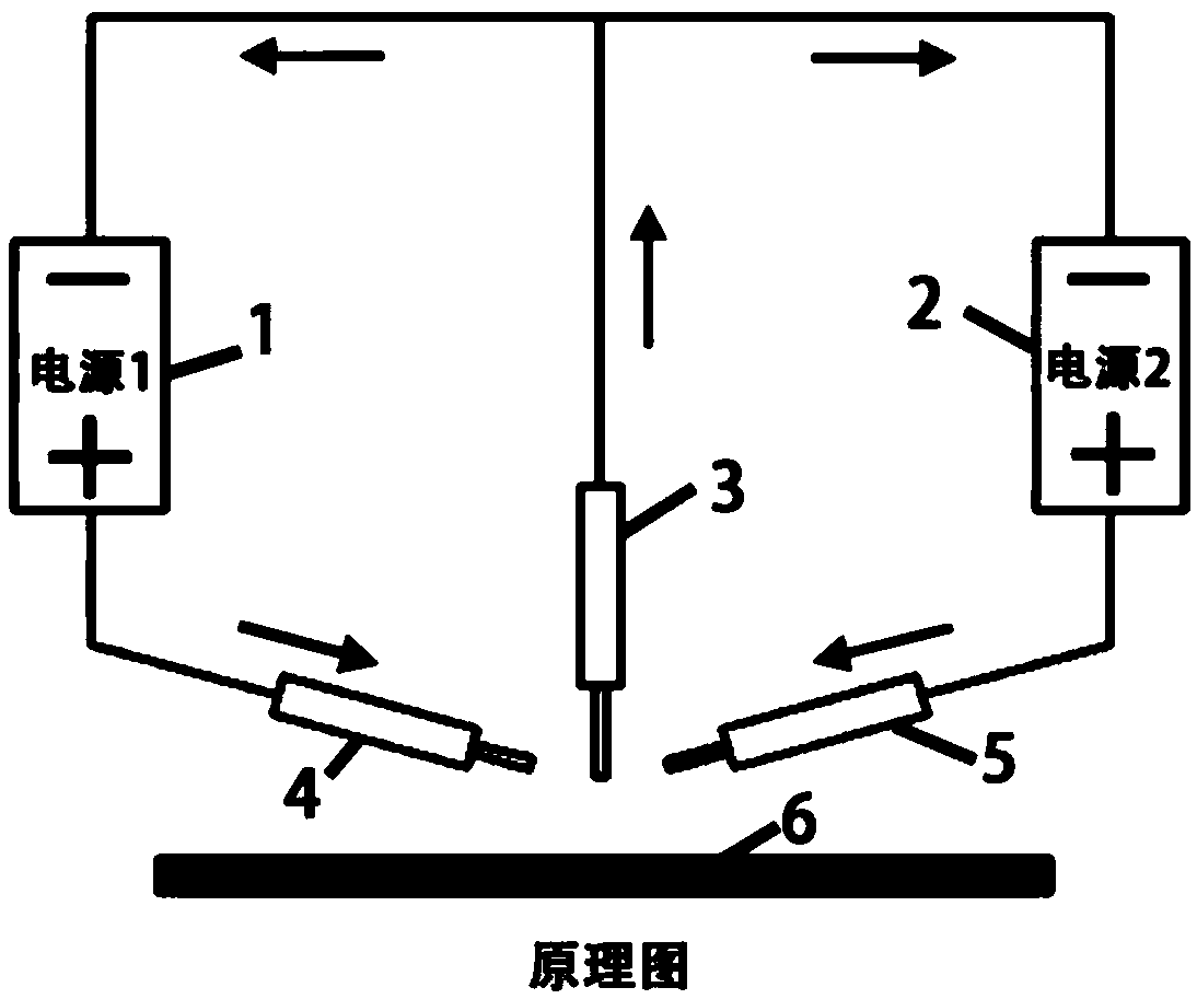
The present invention mainly adopts the mirror-image symmetrical welding wire arrangement mode and the specific welding wire connection mode (that is, the main wire is connected to the positive pole of the power supply, and the side wire is connected to the negative pole of the power supply). The magnetic field strength between them solves the problem of tail deflection of the two indirect arcs during the welding process, improves the arc energy density and arc stiffness, and can realize the effective design and regulation of the welding heat input of the workpiece, thereby improving the application range of this technology

Method used


Image

  • Three-wire gas shielded indirect arc welding method, device and application of method
  • Three-wire gas shielded indirect arc welding method, device and application of method
  • Three-wire gas shielded indirect arc welding method, device and application of method

Examples


Embodiment 1

[0068] Example 1: three-wire gas-shielded indirect arc parallel surfacing.

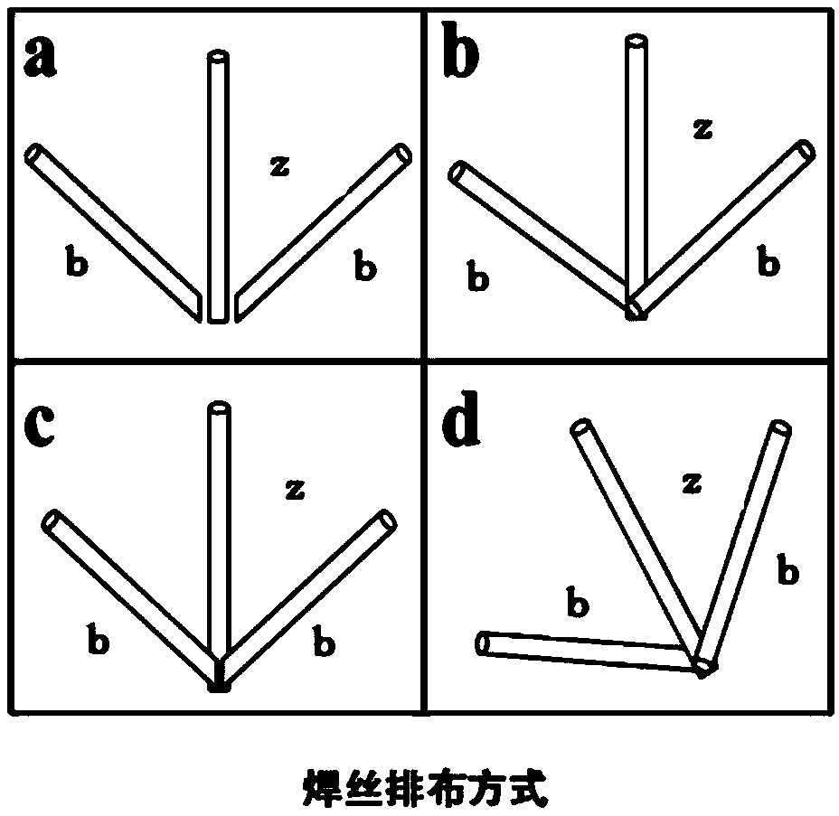
[0069] use Figure 5 The welding wire distribution shown in , the angle between the main wire 3 and the horizontal direction is 45°, the angle between the first side wire 4 and the second side wire 5 and the main wire 3 is 30° respectively, and the two side wires are distributed in the corner of the main wire 3 Both sides are mirror-symmetrical with respect to the main wire, and the two side wires are in contact with the main wire 3 respectively, and the two contact points are on the same horizontal line. Among them, the three steel welding wires are ER50-6, the diameter of the main wire 3 is 1.6mm, and the diameter of both wires is 1.2mm. The power supply uses a DC power supply as the first arc power supply 1 and a pulsed DC power supply as the second arc power supply 2. The corresponding protective gas is 80% CO 2 and 20% Ar mixed gas; plane surfacing welding was carried out on the Q235 steel plat...

Embodiment 2

[0071] Example 2: three-wire gas-shielded indirect arc vertical surfacing.

[0072] use Figure 5 The welding wire distribution shown in , the angle between the main wire 3 and the horizontal direction is 45°, the angle between the two side wires and the main wire 3 is 30°, and the two side wires are distributed on both sides of the main wire 3 and are mirror-symmetrical about the main wire , and the wires on both sides are in contact with the main wire 3 respectively, and the two contact points are on the same horizontal line. Among them, the three steel welding wires are ER50-6, the diameter of the main wire 3 is 1.6mm, and the diameter of both wires is 1.2mm. The power supply adopts a DC power supply and a pulsed DC power supply, and the corresponding shielding gas is 80% CO 2 and 20% Ar mixed gas; plane surfacing welding was carried out on the Q235 steel plate as the base material, the surfacing direction was perpendicular to the vertical surface where the welding wire wa...

Embodiment 3

[0073] Embodiment 3: Single-pass forming gas-shielded three-wire indirect arc welding.

[0074] like Figure 7 , the distribution of the welding wire used is shown in Figure 5 As shown, the angle between the main wire 3 and the side wire is 30 degrees, the main wire diameter is 1.6mm, the diameter of the two side wires is 1.2mm, the welding wire type is ER50-6, the welding base material is Q235 low carbon steel, and the plate size is 300mm ×150mm×10mm, the bevel angle is 20°, no blunt edge, ceramic liner 7 is used on the back, the butt gap is 2mm, the total welding current used is 320A, the welding speed is 735mm / min, and the single pass forming is very good of welded joints. Due to its small groove angle, high welding wire deposition rate and fast welding speed, it has the characteristics of high efficiency.


PUM


Abstract

The invention provides a three-wire gas shielded indirect arc welding method, a device and the application of the method. The method implements the welding process by three welding wires and two arc power supplies and specifically comprises the following steps: before welding, connecting one of the three welding wires to anodes of two arc power supplies, and respectively connecting the other two welding wires to cathodes of two arc power supplies; arranging the welding wire connecting to the anodes of two arc power supplies in the middle as a main wire; respectively arranging the other two welding wires on both sides of the main wire as side wires; enabling orthographic projections of the side wires and the main wire in a plane perpendicular to a welding direction to meet conditions as follows: an included angle between each side wire and the main wire is 0 degree to 5 degrees and two side wires are in a mirror symmetric relationship around the main wire; and when carrying out welding,enabling two arc power supplies to simultaneously output, and according to welding process requirements, implementing the welding process with a high deposition rate and a large penetration depth byoptimizing welding parameters. The three-wire gas shielded indirect arc welding method has the advantages of effectively solving a problem that two indirect arc tails are respectively deflected towards both sides, improving the arc energy density and the like.

Description

technical field [0001] The invention belongs to the technical field of material processing, and relates to an indirect arc welding method, in particular to a three-wire gas-shielded indirect arc welding method, device and application thereof. Background technique [0002] At present, gas metal arc welding has been widely used in various industries, but it is still difficult to meet the needs of the rapid development of modern manufacturing industry. [0003] In recent years, some high-efficiency MIG welding has been proposed and promoted. Among these methods, the key to improving welding efficiency is to increase the welding wire cladding efficiency, that is, to increase the welding current. However, since a loop is formed between the power supply, the workpiece and the welding wire, the current flowing through the welding wire and the workpiece must be equal. Therefore, increasing the welding wire cladding rate by increasing the welding current will inevitably increase th...

Claims


Application Information

Patent Timeline
Patent Type & Authority Applications(China)
IPC IPC(8): B23K9/16B23K9/04
CPCB23K9/04B23K9/16B23K9/025B23K9/1735B23K9/23B23K2103/04B23K9/164
Inventor 刘黎明宋刚张兆栋胡成辉
Owner DALIAN UNIV OF TECH
Learn More