Fixed electric welding machine support for automatic control

A fixed, electric welding machine technology, applied in the direction of manufacturing tools, welding equipment, auxiliary welding equipment, etc., can solve the problems of cumbersome welding parts, no feeding mechanism, single function, etc., and achieve the effect of improving flexibility

Active Publication Date: 2018-12-25
XIANGYANG ZHONGXINGHE AUTO PARTS CO LTD
View PDF4 Cites 0 Cited by
  • Summary
  • Abstract
  • Description
  • Claims
  • Application Information

AI Technical Summary

Problems solved by technology

[0003] The purpose of the present invention is to provide a fixed fixed electric welding machine support for automatic control, to solve the problem that the existing fixed fixed electric welding machine support proposed in the above-mentioned background technology has a single function, and the electric welding method is single, without The auxiliary welding bracket of the traditional and automatic welding method does not have a good feeding mechanism. When processing large-scale welded parts such as automobiles, the welded parts are generally heavy, and it is laborious and cumbersome to manually load materials. The problem of the material feeding and welding integrated mechanism that reduces the physical strength of personnel

Method used


Image

  • Fixed electric welding machine support for automatic control
  • Fixed electric welding machine support for automatic control
  • Fixed electric welding machine support for automatic control

Examples


Embodiment 1

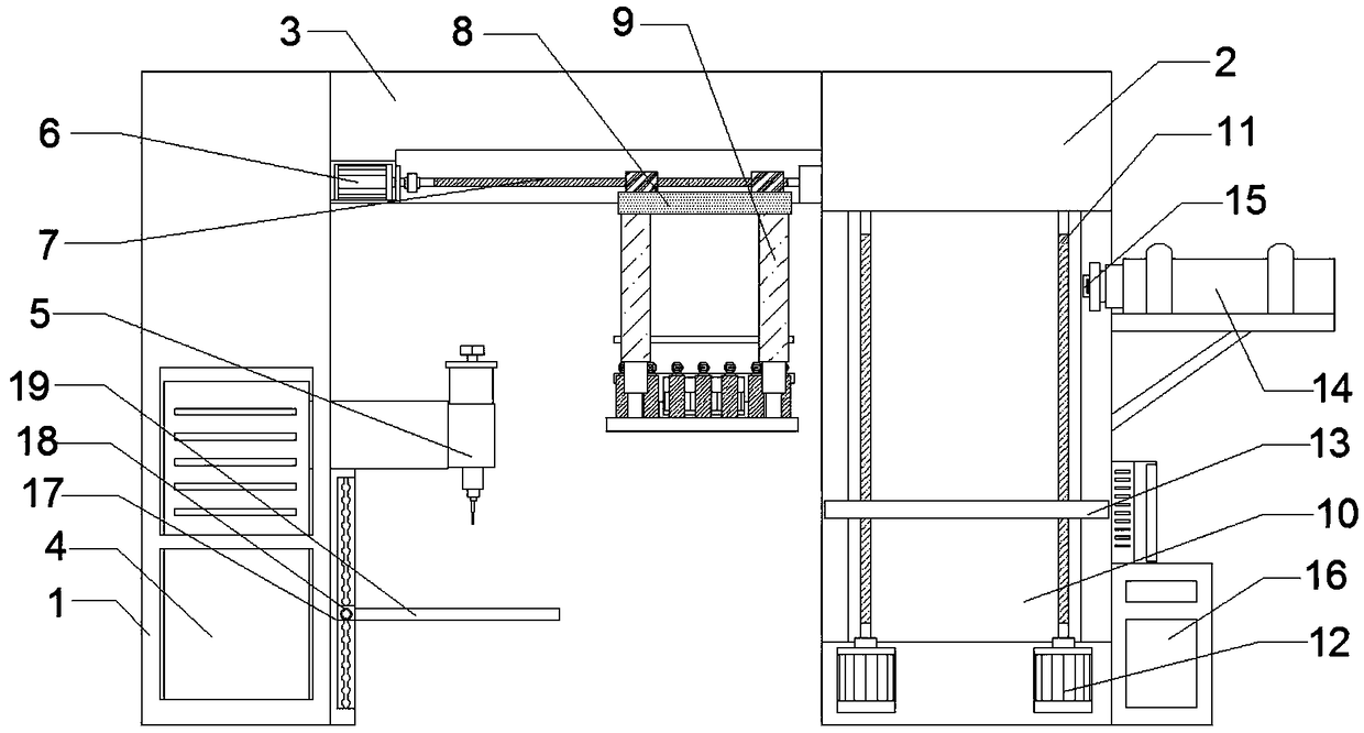
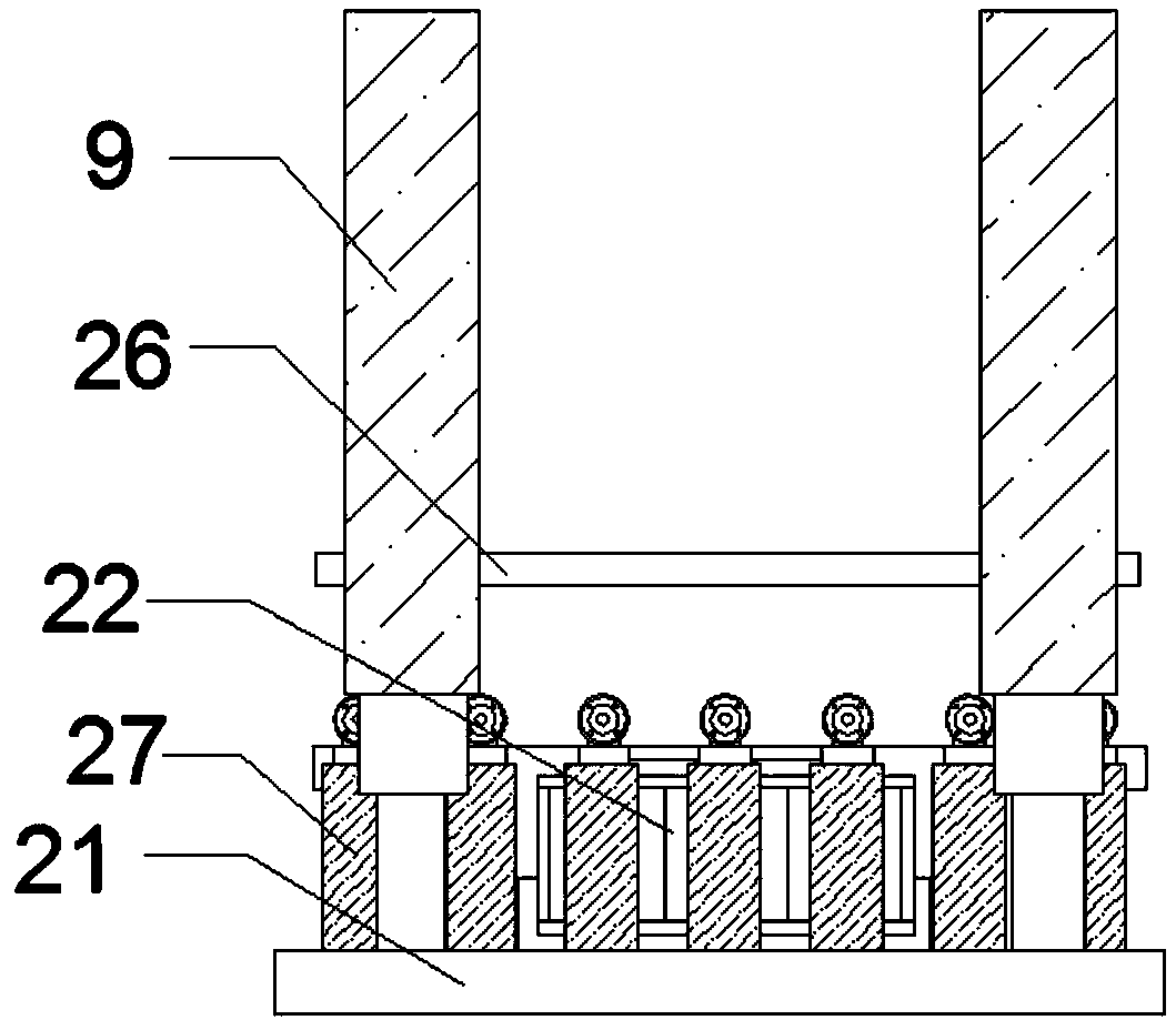
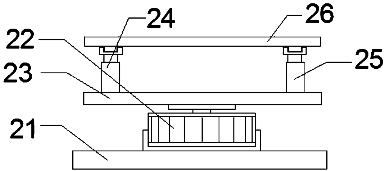
[0022] Such as Figure 1-4 As shown, a fixed fixed electric welding machine support for automatic control includes A frame 1, B frame 2, horizontal frame 3, electric lifting column 9, computer 16 and electric push rod 14, and one end of the horizontal frame 3 The A frame 1 is installed through the support frame, and the B frame 2 is installed on the other end of the cross frame 3 through the support frame. Head 5, the welding head 5 is located on the side of the A frame 1, the bottom of the welding head 5 is installed with a chute 17 through a bolt, and the chute 17 is installed on the A frame 1, and the bottom side of the horizontal frame 3 passes through the protective frame The first forward and reverse drive motor 6 is installed, and the other side of the bottom of the cross frame 3 is installed with the first screw mandrel 7 through the fixed bushing. end connection, the bottom of the first screw rod 7 is installed with a load-bearing plate 8 through a slider, and the bo...

Embodiment 2

[0029] Such as Figure 1-4 As shown, a fixed fixed electric welding machine support for automatic control includes A frame 1, B frame 2, horizontal frame 3, electric lifting column 9, computer 16 and electric push rod 14, and one end of the horizontal frame 3 The A frame 1 is installed through the support frame, and the B frame 2 is installed on the other end of the cross frame 3 through the support frame. Head 5, the welding head 5 is located on the side of the A frame 1, the bottom of the welding head 5 is installed with a chute 17 through a bolt, and the chute 17 is installed on the A frame 1, and the bottom side of the horizontal frame 3 passes through the protective frame The first forward and reverse drive motor 6 is installed, and the other side of the bottom of the cross frame 3 is installed with the first screw mandrel 7 through the fixed bushing. end connection, the bottom of the first screw rod 7 is installed with a load-bearing plate 8 through a slider, and the bo...


PUM


Abstract

The invention discloses a fixed electric welding machine support for automatic control. The fixed electric welding machine support comprises a frame A, a frame B, a cross frame, electric lifting columns, a computer and an electric push rod, wherein the frame A is arranged at one end of the cross frame through a supporting frame; in addition, the frame B is arranged at the other end of the cross frame through the supporting frame; a fixed electric welding machine is arranged at the bottom in the frame A through a protective frame; a welding head is arranged on one side of the top of the fixed electric welding machine and is positioned on one side of the frame A; a sliding chute is formed in the bottom of the welding head through bolts and is also formed in the frame A; a first positive andnegative rotation motor is arranged on one side of the bottom of the cross frame through the protective frame; besides, a first screw is arranged on the other side of the bottom of the cross frame through a fixed shaft sleeve. When a welding part on a feeding plate reaches a detection position of an infrared switch, the detection end of the infrared end is triggered to close the rotation of secondpositive and negative rotation driving motors, so that the ascending work of the feeding plate by second positive and negative rotation driving motors is stopped and further horizontal height of thewelding part on the feeding plate corresponds to an electric push rod.

Description

technical field [0001] The invention belongs to the field of welding technology, and in particular relates to a fixed fixed electric welding machine support for automatic control. Background technique [0002] The existing fixed electric welding machine support has insufficient functionality, and the electric welding method is simplistic. There is no auxiliary welding support for traditional and automated welding methods, and there is no good feeding mechanism. When processing large welded parts such as automobiles, its The welded parts are generally heavy, and it is laborious and cumbersome to manually load the material. There is no good feeding and welding integrated mechanism that can reduce the physical strength of the personnel. Contents of the invention [0003] The purpose of the present invention is to provide a fixed fixed electric welding machine support for automatic control, to solve the problem that the existing fixed fixed electric welding machine support pro...

Claims


Application Information

Patent Timeline
Patent Type & Authority Applications(China)
IPC IPC(8): B23K37/02B23K37/047
CPCB23K37/0252B23K37/047
Inventor 徐曼丽孙海山
Owner XIANGYANG ZHONGXINGHE AUTO PARTS CO LTD
Why Eureka
Try Eureka