
PET detector module, PET detector ring and PET detector array

A detector ring and detector technology, applied in the field of medical equipment, can solve the problems of large gaps and large proportion of invalid space in PET equipment, etc.

Active Publication Date: 2018-12-25
SHANGHAI UNITED IMAGING HEALTHCARE
View PDF12 Cites 1 Cited by
  • Summary
  • Abstract
  • Description
  • Claims
  • Application Information

AI Technical Summary

Problems solved by technology

[0003] However, for the design of traditional detector modules, in the axial direction of the PET detector ring, the gap between the crystals of the detector module is often relatively large, resulting in a large proportion of invalid space in the PET device

Method used


Image

  • PET detector module, PET detector ring and PET detector array
  • PET detector module, PET detector ring and PET detector array
  • PET detector module, PET detector ring and PET detector array

Examples


Embodiment Construction

[0028] In order to make the purpose, technical solution and advantages of the present application clearer, the present application will be further described in detail below in conjunction with the accompanying drawings and embodiments. It should be understood that the specific embodiments described here are only used to explain the present application, and are not intended to limit the present application.

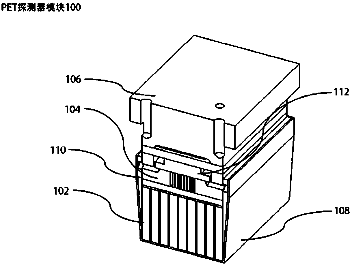
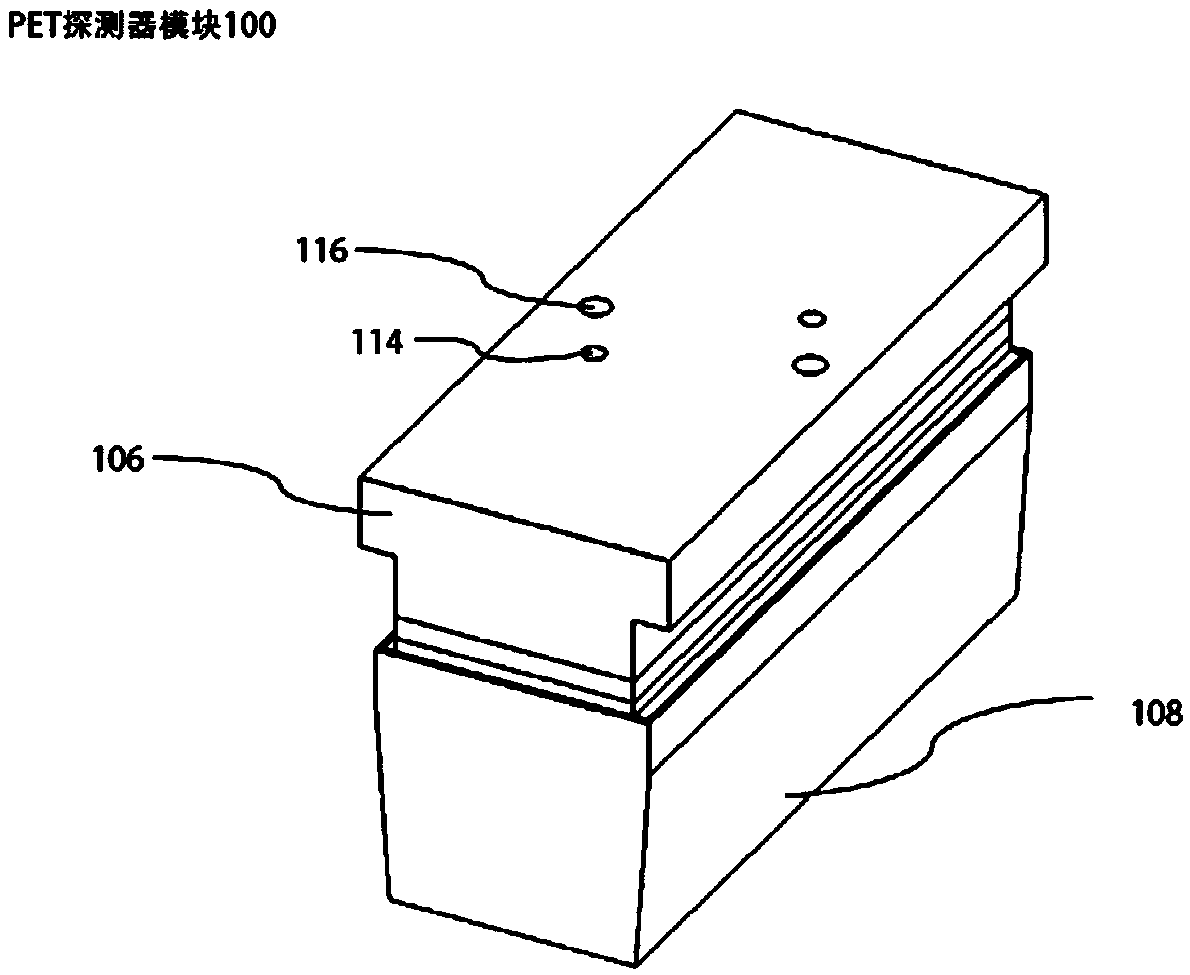
[0029] figure 1 It is a schematic diagram of the cross-sectional structure of the PET detector module in one embodiment, such as figure 1 As shown, a PET detector module 100 is used to combine to form a PET detector ring. The PET detector module 100 includes: a detector crystal 102, a connecting plate 104 and a fixing block 106;

[0030] Wherein, the fixed block 106 is stacked on the detector crystal 102 along the radial direction away from the PET detector ring through the connecting plate 104, and the length of the fixed block 106 in the axial direction of the PET detec...


PUM


Abstract

The invention relates to a PET detector module, a PET detector ring and a PET detector array. The PET detector module is used for forming the PET detector ring in a combining mode. The PET detector module comprises a detector crystal, a connecting plate and a fixing block. The fixing block is arranged on the detector crystal in a stacking mode in the radial direction of the PET detector ring by the connecting plate. The length, in the axial direction of the PET detector ring, of the fixing block is less than the length, in the axial direction of the PET detector ring, of the detector crystal.Two end faces of the fixing block are located in the limited area range of the two ends faces of the detector crystal. The PET detector module positions the fixing block on the detector crystal in a stacking mode by the connecting plate, and therefore spare supporting or fixing structures in the axial direction of the PET detector ring are omitted. In this way, when a plurality of the PET detectorrings are applied in a combining mode, in the axial direction of the PET detector ring, distance among the detector crystals of the adjacent PET detector rings is small enough, and invalid space in PET equipment is reduced.

Description

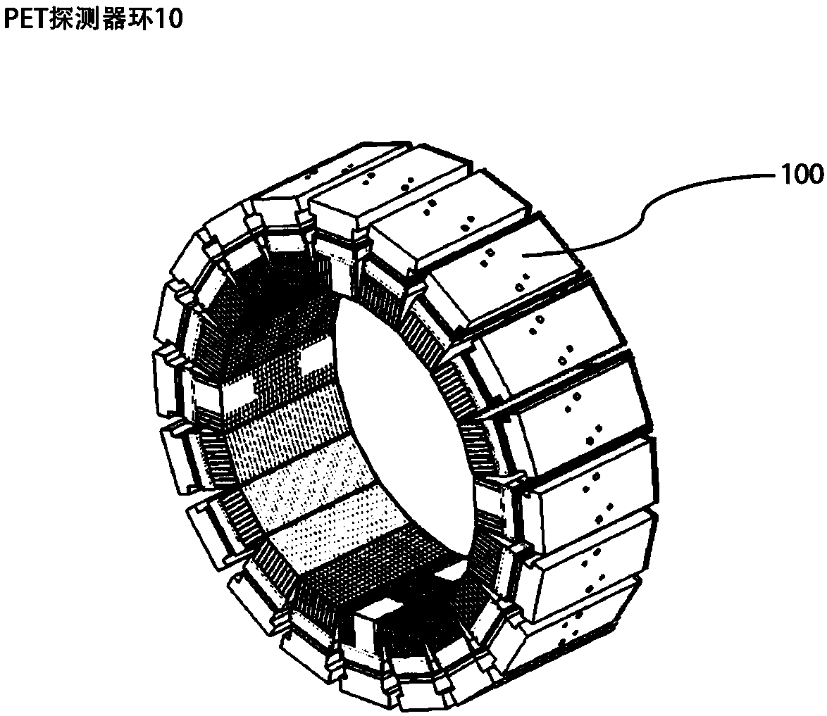
technical field [0001] The invention relates to the field of medical equipment, in particular to a PET detector module, a PET detector ring and a PET detector array. Background technique [0002] When performing positron emission computed tomography (PET for short), in order to expand the scanning range, multiple PET stents can be combined into a PET array along its axial direction, wherein each PET detector ring is composed of multiple The detector modules form a ring shape, and each detector module is provided with a crystal that receives a high-energy photon signal and converts it into a low-energy visible light signal. [0003] However, for the design of the traditional detector module, the gap between the crystals of the detector module is often relatively large in the axial direction of the PET detector ring, resulting in a relatively large proportion of invalid space in the PET device. Contents of the invention [0004] Based on this, it is necessary to provide a P...

Claims


Application Information

Patent Timeline
Patent Type & Authority Applications(China)
IPC IPC(8): G01T1/29
CPCG01T1/2985
Inventor 李淼蒋华伟
Owner SHANGHAI UNITED IMAGING HEALTHCARE
Learn More