
A silent motor for cervical spine massager
A massager and mute technology, applied in electromechanical devices, electrical components, electric components, etc., can solve problems such as high-frequency vibration and noise, user discomfort, etc., to reduce vibration and noise, improve comfort, and speed up cycle efficiency Effect
- Summary
- Abstract
- Description
- Claims
- Application Information
AI Technical Summary
Problems solved by technology
Method used
Image

Examples
Embodiment Construction
[0020] The standard parts used in the present invention can be purchased from the market, and the special-shaped parts can be customized according to the instructions and the accompanying drawings. The specific connection methods of each part adopt mature bolts, rivets, welding in the prior art , pasting and other conventional means, no longer described in detail here.
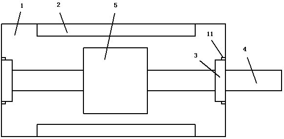
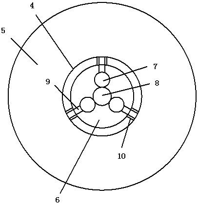
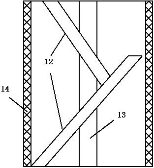
[0021] refer to Figure 1-6 , a specific embodiment of the present invention includes a casing 1, a stator 2 is fixed inside the casing 1, an output shaft 4 is installed at both ends of the casing 1 through bearings 3, a rotor 5 is installed on the output shaft 4, and a rotor 5 is mounted on the output shaft 4. A cavity 6 is provided, and three rubber columns 7 are arranged in a ring in the cavity 6, and the two ends of the rubber columns 7 are fixedly connected with the top and bottom of the cavity 6 respectively, and the three rubber columns 7 are connected by an annular spring body 8 The inner wall of the ...
PUM
 Abstract
Description
Claims
Application Information