Plate cutting machine and plate cutting method

A cutting machine and plate technology, applied in shearing device, shearing machine equipment, metal processing equipment and other directions, can solve the problems of affecting the quality of the plate, affecting the cutting effect of the plate, laborious plate, etc., to improve the cutting efficiency, reasonable design, Guaranteed cutting effect

Inactive Publication Date: 2018-12-28
大连范特西西科技有限公司
View PDF5 Cites 1 Cited by
  • Summary
  • Abstract
  • Description
  • Claims
  • Application Information

AI Technical Summary

Problems solved by technology

[0002] After the plate is formed, the edge of the plate needs to be cut longitudinally, so as to remove the unusable parts of the edge and trim the edge of the plate. At this time, a plate cutting device needs to be used. The plate cutting device or plate cutting machine in the prior art is practical. There are still some disadvantages, such as the need to use manpower to push the plate forward, which is more laborious and may cause the plate to shift, which will affect the cutting effect of the plate. At the same time, there will be some friction between the plate and the cutting platform, and scratches will appear on the bottom of the plate When the scratch is deep, it will affect the quality of the board and the subsequent use

Method used


Image

  • Plate cutting machine and plate cutting method
  • Plate cutting machine and plate cutting method
  • Plate cutting machine and plate cutting method

Examples


Embodiment 1

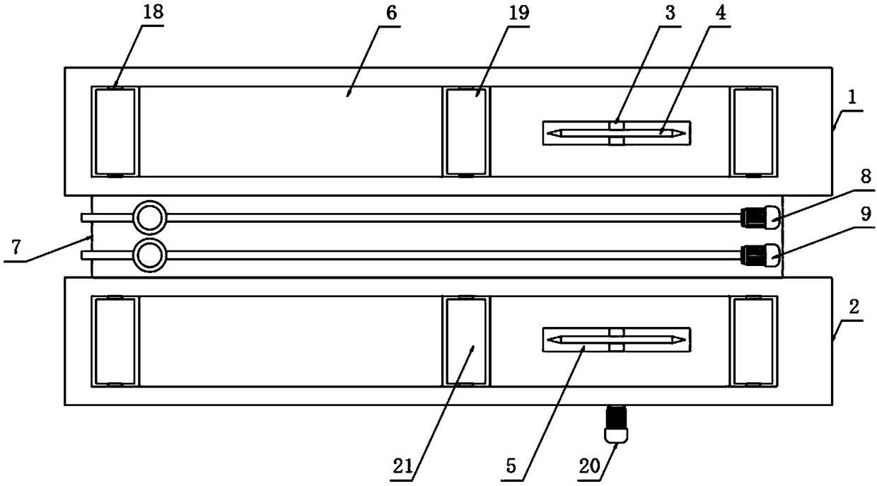
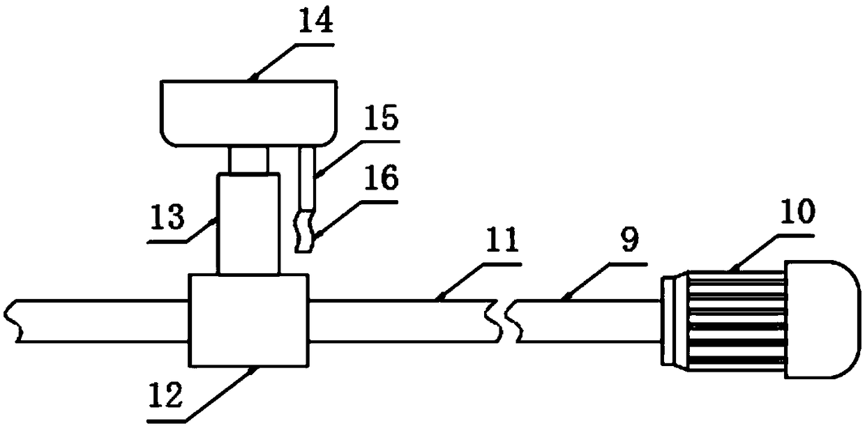
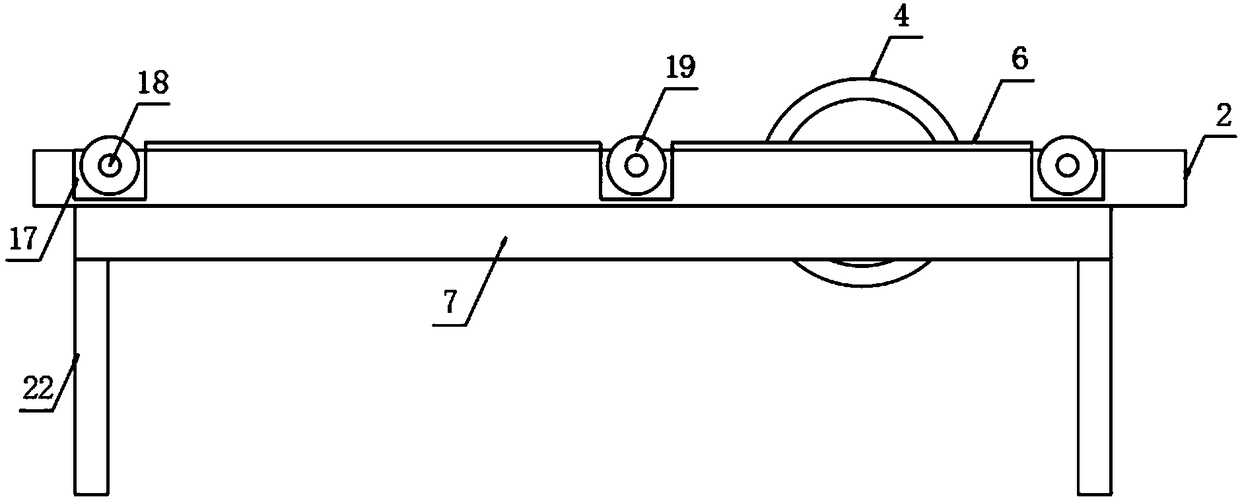
[0024] The present invention provides such Figure 1-3 A kind of plate cutting machine shown, comprises left side cutting platform 1 and right side cutting platform 2, and described right side cutting platform 2 is arranged on the side of left side cutting platform 1, and described left side cutting platform 1 and right side cutting platform The top of the platform 2 is provided with a rubber pad 6 and the bottom is fixedly provided with a bearing base plate 7, and the top of the bearing base plate 7 is provided with a first plate traveling mechanism 8 and a second plate traveling mechanism 9, and the first plate traveling mechanism 8 and the second The plate traveling mechanism 9 includes a first motor 10, the first motor 10 is provided with a screw 11, the outer side of the screw 11 is sleeved with a mounting block 12, and the top of the mounting block 12 is fixed with a cylinder 13, The top of the cylinder 13 is fixed with a rubber suction head 14, the rubber suction head 1...

Embodiment 2

[0035] A plate cutting method, including the plate cutting machine, also includes the following steps:

[0036] S1: Place the plate on the top of the left cutting platform 1 and the right cutting platform 2, so that the end of the plate is in contact with the edge of the cutting tool 4, and after adjusting the position of the plate, use the vacuum pump at the end of the hose 16 to generate suction;

[0037] S2: Then control the extension of the cylinder 13, so that the rubber suction head 14 is adsorbed on the bottom of the plate;

[0038] S3: Then start the first motor 10 and the second motor 20, the first motor 10 drives the second plate traveling mechanism 9 to rotate forward and reverse, so that the mounting block 12 on the second plate traveling mechanism 9 drives the rubber on the top of the cylinder 13 The suction head 14 moves left or right, and the rubber suction head 14 drives the plate to move together;

[0039] S4: When the rubber suction head 14 drives the board ...


PUM


Abstract

The invention discloses a plate cutting machine and a plate cutting method. The plate cutting machine comprises a left cutting platform and a right cutting platform, the right cutting platform is arranged on one side of the left cutting platform, a rubber pad is arranged on the top of each of the left cutting platform and the right cutting platform, a bearing bottom plate is fixedly arranged at the bottom of each of the left cutting platform and the right cutting platform, each of a first plate moving mechanism and a second plate moving mechanism are arranged at the bottom of the bearing bottom plate and comprises a first motor, a screw rod is arranged on each first motor, a mounting block sleeves each screw rod, an air cylinder is fixedly arranged at the top of each mounting block, a rubber sucker is fixedly arranged at the top of each air cylinder, an air suction pipe is arranged on each rubber sucker, and a hose is arranged at the end of each air suction pipe. The plate cutting machine is reasonable in design, more labor saving in plate machining, capable of avoiding plate deviation and ensuring the plate cutting effect and highly practical.

Description

technical field [0001] The invention relates to the technical field of manufacturing energy-saving building materials and green building materials, in particular to a plate cutting machine and method. Background technique [0002] After the plate is formed, the edge of the plate needs to be cut longitudinally, so as to remove the unusable parts of the edge and trim the edge of the plate. At this time, a plate cutting device needs to be used. The plate cutting device or plate cutting machine in the prior art is practical. There are still some disadvantages, such as the need to use manpower to push the plate forward, which is more laborious and may cause the plate to shift, which will affect the cutting effect of the plate. At the same time, there will be some friction between the plate and the cutting platform, and scratches will appear on the bottom of the plate When the scratches are deep, it will affect the quality of the board and the subsequent use. [0003] Therefore, ...

Claims


Application Information

Patent Timeline
Patent Type & Authority Applications(China)
IPC IPC(8): B23D19/04
CPCB23D19/04
Inventor 安庆文
Owner 大连范特西西科技有限公司
Why Eureka
Try Eureka